Firmly-arranged decelerator

A speed reducer, a stable technology, applied in the direction of mechanical equipment, transmission parts, belts/chains/gears, etc., can solve the problems of poor placement stability, loosening of fixing screws, single positioning method, etc., to avoid offset, structure Simple, easy-to-use effects

Active Publication Date: 2018-09-14
浙江昆博机械制造股份有限公司
View PDF5 Cites 2 Cited by
  • Summary
  • Abstract
  • Description
  • Claims
  • Application Information

AI Technical Summary

Problems solved by technology

It plays the role of matching speed and transmitting torque between the prime mover and the working machine or the actuator. It is widely used in modern machinery. The existing reducer is usually fixed by screws, and the stability of the installation is poor. Long-term vibration is easy to cause the screw to be fixed. Due to vibration loosening and the movement of the position of the reducer, after the existing reducer is installed and fixed, the stability of the reducer is poor due to the single positioning method, so a stable reducer is needed to meet people's needs

Method used


Image

  • Firmly-arranged decelerator
  • Firmly-arranged decelerator
  • Firmly-arranged decelerator

Examples


Embodiment Construction

[0018] The following will clearly and completely describe the technical solutions in the embodiments of the present invention with reference to the accompanying drawings in the embodiments of the present invention. Obviously, the described embodiments are only some, not all, embodiments of the present invention.

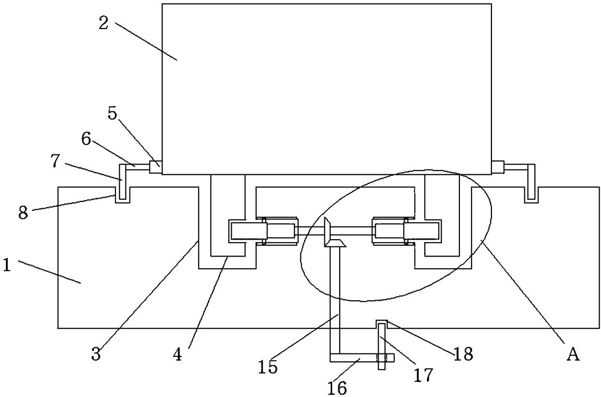
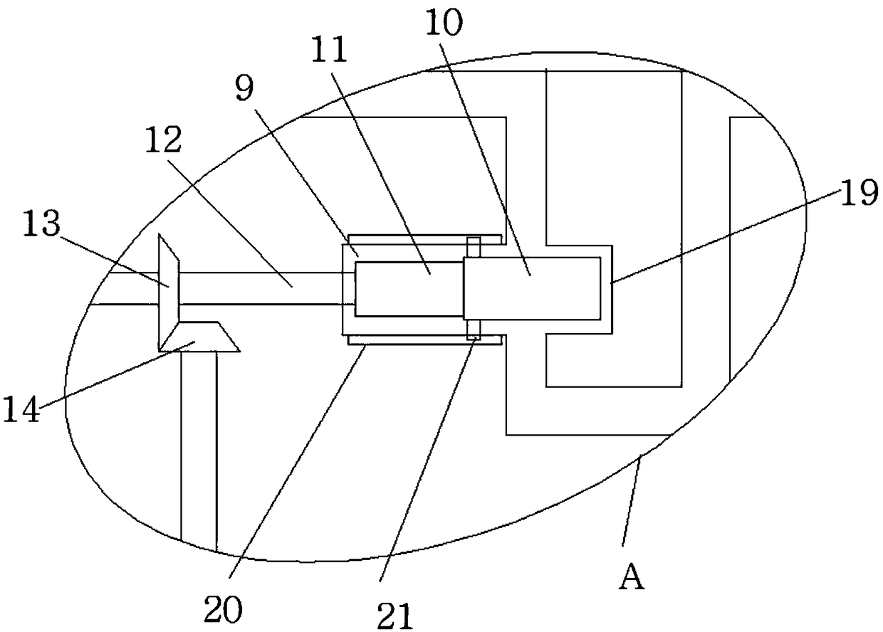
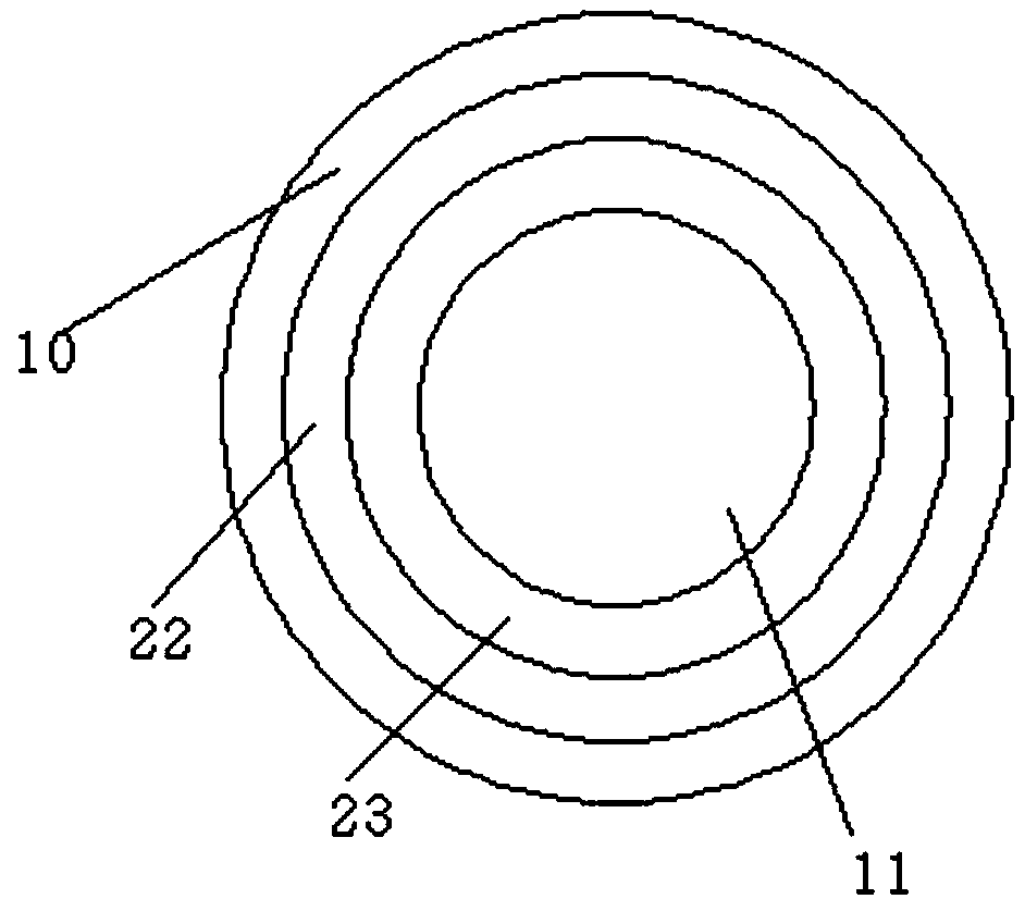
[0019] refer to Figure 1-3 , a kind of stable reducer, including a bracket 1, a reducer body 2 is movably installed on the top side of the bracket 1, two installation grooves 3 are opened on the top side of the bracket 1, and fixed feet 4 are movably installed in the installation grooves 3, The top side of the fixed foot 4 is fixedly connected with the bottom side of the reducer body 2, and the inner wall of the side where the two installation grooves 3 are close to each other is provided with a groove 9, and a sleeve 10 is movably installed in the groove 9, and the sleeve 10 One end of each extends to the outside of the groove 9, and is movably connected with the f...


PUM


Abstract

The invention discloses a firmly-arranged decelerator which comprises a support. A decelerator body is movably mounted on the top side of the support, two mounting grooves are formed in the top side of the support, and fixing feet are movably mounted in the mounting grooves correspondingly; the top sides of the fixing feet are fixedly connected with the bottom side of the decelerator body, and grooves are formed in the inner walls of the sides, close to each other, of the two mounting grooves correspondingly; sleeves are movably mounted in the grooves, and one end of each sleeve extends out ofthe corresponding groove and is movably connected with the corresponding fixing foot; and screw rods are connected into the two sleeves in a threaded mode correspondingly, the ends, close to each other, of the two screw rods both extend out of the sleeves and are fixedly connected with a same rotating shaft. In the firmly-arranged decelerator, the decelerator body is fixed through the screw rodsand rotating rods when firmly mounted, a traditional screw fixing mode is avoided, and the decelerator body is arranged more firmly; and meanwhile, through positioning of the two sides, the offset problem in the working process of the decelerator body is effectively avoided, the structure is simple, and using is convenient.

Description

technical field [0001] The invention relates to the technical field of speed reducers, in particular to a stable speed reducer. Background technique [0002] The reducer is an independent component composed of gear transmission, worm drive, and gear-worm drive enclosed in a rigid shell. It is often used as a reduction transmission device between the prime mover and the working machine. The reducer is generally used for low-speed High-torque transmission equipment, the electric motor, internal combustion engine or other high-speed running power is used to achieve the purpose of deceleration through the gear with a small number of teeth on the input shaft of the reducer meshing with the large gear on the output shaft. It plays the role of matching speed and transmitting torque between the prime mover and the working machine or the actuator. It is widely used in modern machinery. The existing reducer is usually fixed by screws, and the stability of the installation is poor. Lon...

Claims


Application Information

Patent Timeline
Patent Type & Authority Applications(China)
IPC IPC(8): F16H57/025
CPCF16H57/025Y02E10/50
Inventor 吴顺龙
Owner 浙江昆博机械制造股份有限公司
Why Eureka
Try Eureka