Pressure visualization device, manufacturing method thereof and detection equipment

A detection equipment and pressure technology, applied in the detection field to achieve the effect of visualization

Active Publication Date: 2018-09-14
BOE TECH GRP CO LTD +1
View PDF12 Cites 17 Cited by
  • Summary
  • Abstract
  • Description
  • Claims
  • Application Information

AI Technical Summary

Problems solved by technology

[0005] The purpose of the present disclosure is to provide a pressure visualization device, its preparation method, and detection

Method used


Image

  • Pressure visualization device, manufacturing method thereof and detection equipment
  • Pressure visualization device, manufacturing method thereof and detection equipment
  • Pressure visualization device, manufacturing method thereof and detection equipment

Examples


Example Embodiment

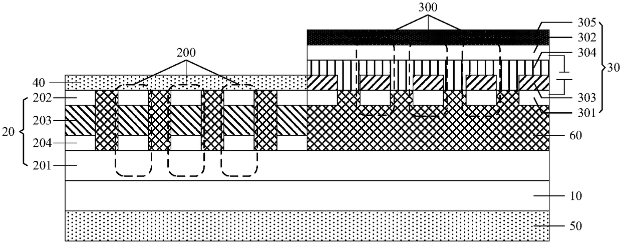
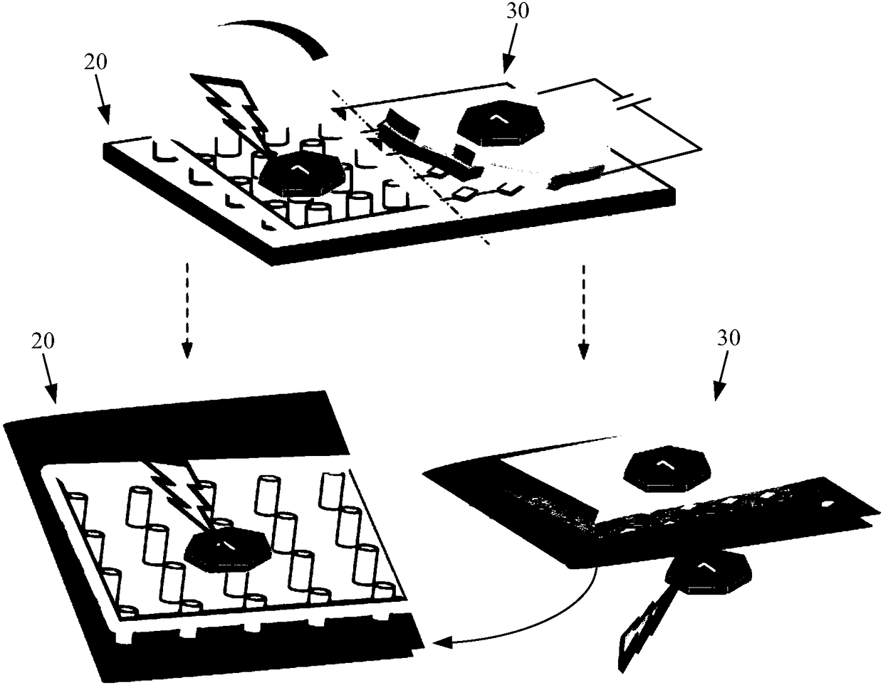
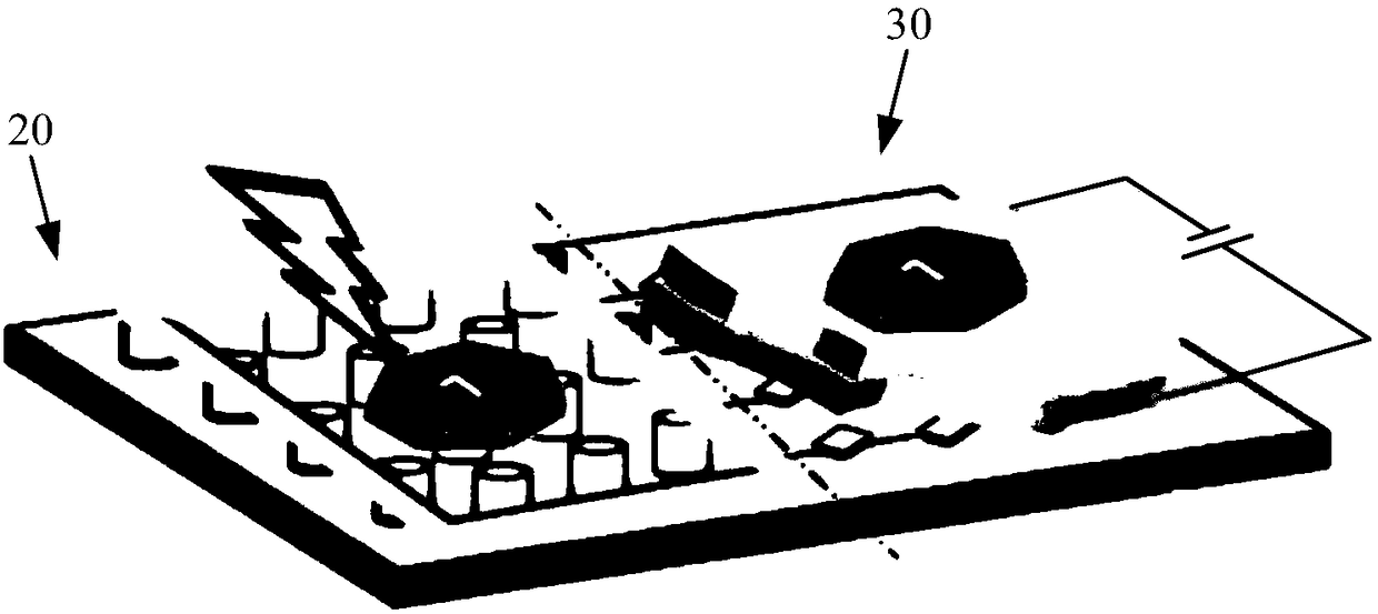
[0053]Example embodiments will now be described more fully with reference to the accompanying drawings. Example embodiments may, however, be embodied in many forms and should not be construed as limited to the examples set forth herein; rather, these embodiments are provided so that this disclosure will be thorough and complete and will fully convey the concept of example embodiments to those skilled in the art. The described features, structures, or characteristics may be combined in any suitable manner in one or more embodiments.

[0054] Furthermore, the drawings are merely schematic illustrations of the present disclosure and are not necessarily drawn to scale. The same reference numerals in the drawings denote the same or similar parts, and thus repeated descriptions thereof will be omitted. Some of the block diagrams shown in the drawings are functional entities and do not necessarily correspond to physically or logically separate entities. These functional entities m...


PUM


Abstract

The invention provides a pressure visualization device, a manufacturing method thereof and detection equipment, which relate to the technical field of detection. The pressure visualization device comprises a flexible substrate, a piezoelectric module and an electrochromic module which are located on one surface of the flexible substrate and are arranged adjacently, a first attaching layer locatedon one surface, away from the flexible substrate, of the piezoelectric module and a second attaching layer located on the other surface of the flexible substrate, wherein the piezoelectric module comprises multiple piezoelectric units, and the piezoelectric unit comprises a first electrode, a second electrode and a piezoelectric layer located between the first electrode and the second electrode; the electrochromic module comprises multiple electrochromic units, and the electrochromic unit comprises a third electrode, a fourth electrode and an electrochromic layer and an ion transport layer located between the third electrode and the fourth electrode; and the second electrode and the third electrode are electrically connected, and the fourth electrode is a transparent electrode. The pressure visualization device is delicate and portable and can instantly display a pressure signal curve.

Description

technical field [0001] The present disclosure relates to the technical field of detection, in particular to a pressure visualization device, a preparation method thereof, and detection equipment. Background technique [0002] A traditional pressure detection system mainly includes a pressure sensor and a display. During the detection process, it is necessary to record the signal detected by the pressure sensor in real time, then draw a pressure curve according to the recorded signal, and finally display the drawn pressure curve through the monitor to reflect the pressure change process. [0003] However, when the pressure sensor is not properly connected to the display, the pressure detection system cannot realize pressure detection, and the display is relatively large, so the traditional pressure detection system still has the problem of not being portable enough. [0004] It should be noted that the information disclosed in the above background section is only for enhanci...

Claims


Application Information

Patent Timeline
IPC IPC(8): G01L1/24G01L1/14
CPCG01L1/14G01L1/24G01L1/16A61B5/022A61B5/6801A61B2562/0247G02F1/153H10N30/878H10N30/10513H10N30/1061H10N30/10516H10N30/302H10N30/071G02F1/1524A61B5/318G01L9/08G01L19/08G02F1/155G02F1/163H10N30/01H10N30/853
Inventor 李砚秋
Owner BOE TECH GRP CO LTD
Why Eureka
Try Eureka