
A method of compensating the residual magnetic field inside the magnetic shield of laser atomic magnetometer

A technology of residual magnetic field and atomic magnetic force, applied in the size/direction of the magnetic field, using magneto-optical equipment for magnetic field measurement, magnetic field offset compensation, etc., can solve problems affecting the effect of magnetic field compensation

Active Publication Date: 2019-08-16
WUHAN INST OF PHYSICS & MATHEMATICS CHINESE ACADEMY OF SCI
View PDF7 Cites 0 Cited by
  • Summary
  • Abstract
  • Description
  • Claims
  • Application Information

AI Technical Summary

Problems solved by technology

The above methods all use a three-axis magnetic field coil to offset the residual magnetic field, but, i) there may be some non-orthogonality in the lining body of the three-axis magnetic field coil during processing and coil winding, and ii) during the coil installation process, the There will also be a certain angle between the axis direction and the laser propagation direction
These two kinds of non-orthogonality will directly affect the magnetic field compensation effect

Method used


Image

  • A method of compensating the residual magnetic field inside the magnetic shield of laser atomic magnetometer
  • A method of compensating the residual magnetic field inside the magnetic shield of laser atomic magnetometer
  • A method of compensating the residual magnetic field inside the magnetic shield of laser atomic magnetometer

Examples


Embodiment Construction

[0029] Below in conjunction with specific embodiment, and figure 1 — Figure 5 , to further illustrate the present invention.

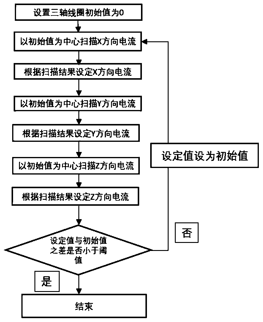
[0030] In this embodiment, the alkali metal atom vapor bubble 7 is used as the cesium atom vapor bubble, Figure 5It is a structural schematic diagram of a single-beam laser atomic magnetometer, and the cesium atom vapor bubble is located at the inner center of the magnetic shield 4 . The 894nm laser beam emitted by the laser 1 propagates along the X axis, and is amplitude modulated by the acousto-optic modulator 2 , the modulation frequency is given by the lock-in amplifier 10 , and the modulated 894nm laser beam passes through the polarizer 3 into linearly polarized light. After the 894nm laser passes through the cesium atom vapor bubble placed in the center of the magnetic shield, the laser is decomposed into two beams orthogonally by the polarization beam splitter prism 8, and the laser polarization plane is obtained by detecting the change of t...


PUM


Abstract

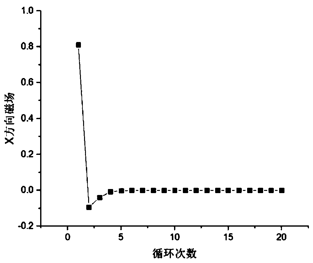
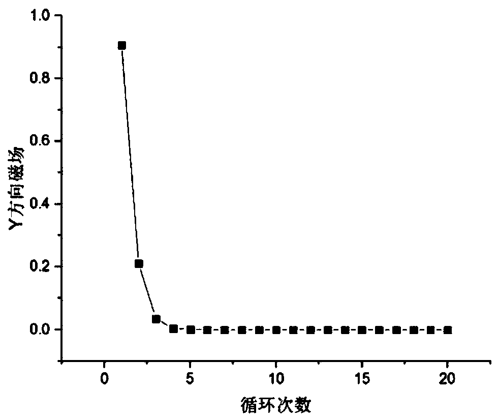
The invention proposes a method for compensating a residual magnetic field inside a magnetic shielding case of a laser atomic magnetometer so that the residual magnetic field inside the magnetic shielding case can be reduced or eliminated and thus the laser atomic magnetometer is able to measure the flux weakening with high sensitivity. The invention provides a method for compensating a residual magnetic field inside a magnetic shielding case of a laser atomic magnetometer, so that problems that the sensitivity of the laser atomic magnetometer is affected because the small-angle non-orthogonality of the three-axis coil exits and the laser propagation direction is not overlapped with the spindle of the magnetic field completely in the actual operation are solved. Internal currents in a three-axis coil are adjusted circularly by multiple times; observation and fitting of a laser atomic magnetometer signal are carried out; and the residual magnetic field strength at the alkali metal atomic vapor bubble inside the magnetic shielding case is reduced or eliminated finally.

Description

technical field [0001] The invention relates to a method for compensating the residual magnetic field inside the magnetic shield of a laser atomic magnetometer, and belongs to the technical field of weak magnetic detection and uniform magnetic field coils. Background technique [0002] One type of laser atomic magnetometer is based on a quantum mechanical phenomenon called nonlinear magneto-optical effects (NMOE) between alkali metal atoms and laser light. The resulting signal has a very narrow linewidth , and within a certain magnetic field range, the polarization plane of the laser is linearly deflected with the magnitude of the magnetic field, so it has extremely high magnetic sensitivity and can be widely used in the study of magnetic phenomena in multiple disciplines and fields. So far, the Romalis research group at Princeton University has successfully achieved 0.16fT / Hz using an atomic magnetometer 1 / 2 Magnetic field measurement sensitivity [Appl.Phys.Lett.97(15), 15...

Claims


Application Information

Patent Timeline
Patent Type & Authority Patents(China)
IPC IPC(8): G01R33/032G01R33/00
CPCG01R33/0017G01R33/032
Inventor 周欣李桐孙献平赵修超朱茂华刘买利叶朝辉
Owner WUHAN INST OF PHYSICS & MATHEMATICS CHINESE ACADEMY OF SCI
Learn More