Communication tower convenient to adjust and mount for mobile communication

A technology of mobile communication and communication tower, applied in the field of mobile communication, can solve the problems of large area of ​​cable-stayed steel wire, poor anti-vibration ability, manual height adjustment, etc. The effect of testing and installation

Active Publication Date: 2018-09-18
湖南省通信建设有限公司
View PDF7 Cites 13 Cited by
  • Summary
  • Abstract
  • Description
  • Claims
  • Application Information

AI Technical Summary

Problems solved by technology

[0002] In the process of infrastructure construction in the field of mobile communication, the communication tower is the infrastructure with the largest construction volume and the highest erection density. The traditional communication tower is composed of steel components such as tower body, platform, lightning rod, ladder, antenna support, etc., and is hot-plated Zinc anti-corrosion treatment, mainly used for transmission and emission of microwave, ultrashort wave, wireless network signals, etc. The downtilt angle of the antenna determines the coverage and signal strength of the signal. The downtilt angle of the traditional antenna is adjusted and fixed during installation. When debugging or changing the downtilt angle of the antenna, manual adjustment is required, which is cumbersome and dangerous to operate. In addition, when installing communication towers, especially communication towers with poles on the roof, it is necessary to use bolts and use cable-stayed steel wires or inclined support rods. Auxiliary support is troublesome to install, the cable-stayed steel wire occupies a large area, and the anti-vibration ability is not good

Method used


Image

  • Communication tower convenient to adjust and mount for mobile communication
  • Communication tower convenient to adjust and mount for mobile communication
  • Communication tower convenient to adjust and mount for mobile communication

Examples


Embodiment Construction

[0018] The following will clearly and completely describe the technical solutions in the embodiments of the present invention with reference to the accompanying drawings in the embodiments of the present invention. Obviously, the described embodiments are only some, not all, embodiments of the present invention. Based on the embodiments of the present invention, all other embodiments obtained by persons of ordinary skill in the art without making creative efforts belong to the protection scope of the present invention.

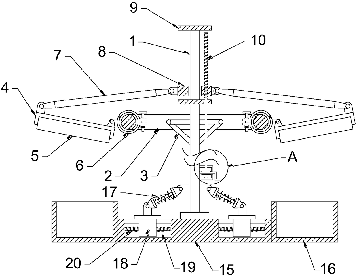
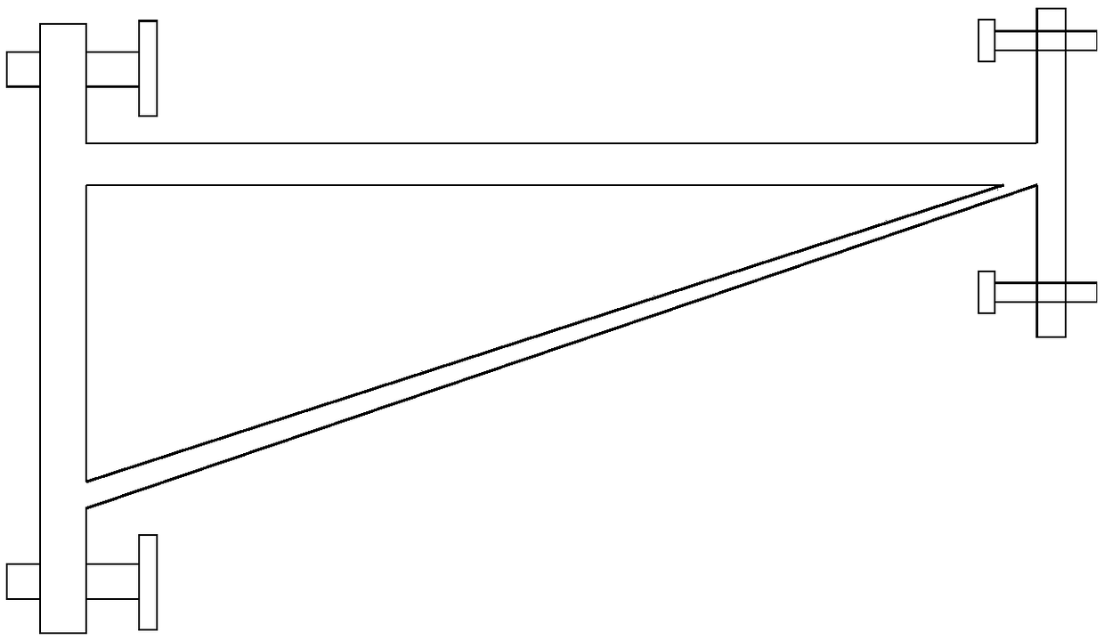
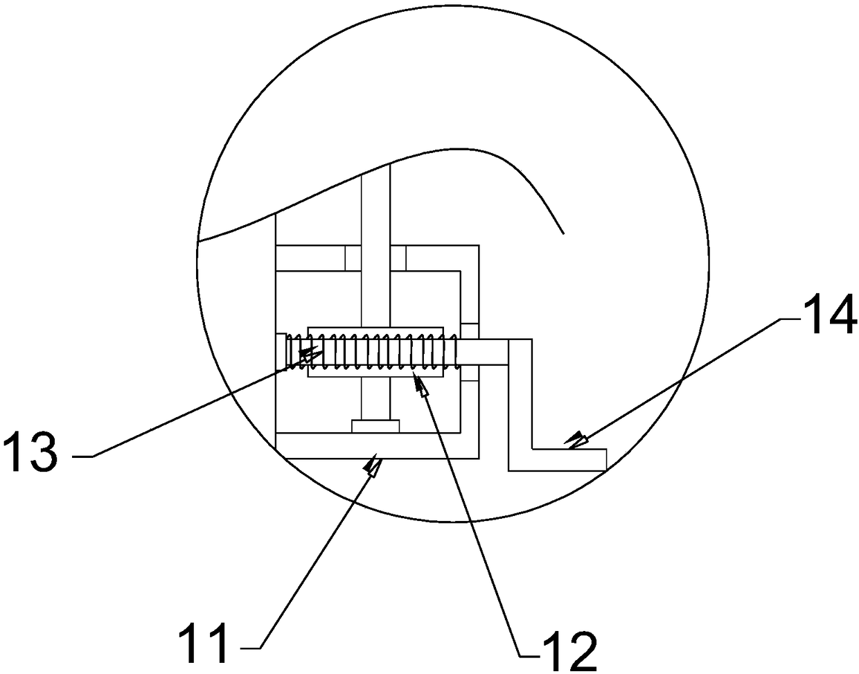
[0019] see Figure 1~2 , in an embodiment of the present invention, a communication tower for mobile communication that is convenient to adjust and install, including a tower rod 1, an antenna 5 and a base 15; The ring-shaped steel structure can mount more antennas at all angles. The inner side of the ring-shaped pole 2 is fixedly connected with the tower pole 1 through the triangular support frame 3 distributed in a circle, so as to improve the stability of t...


PUM


Abstract

The invention discloses a communication tower convenient to adjust and mount for mobile communication. The communication tower comprises a tower rod, antennas and a base. The tower rod is sleeved withan annular holding rod; the antennas are arranged on the outer side of the annular holding rod in a circumferential mode; the outer side of each antenna is fixedly provided with an antenna bracket; the lower end of each antenna bracket is hinged to a holding hoop; each holding hoop is arranged on the corresponding annular holding rod in a sleeving mode; the upper end of each antenna bracket is hinged to a connecting rod; and the upper end of each connecting rod is hinged to a movable disc. The antenna brackets is arranged in a linkage mode with turbine wheels and turbine rods, the erecting angle in the vertical direction of the antenna is conveniently and labor-savingly adjusted by rotating a handle, testing and mounting are convenient, and adjusting at a high altitude is avoided; annularholding rods are arranged to increase hanging loads of the antennas, and the horizontal direction of the antennas can be conveniently adjusted; and a weight box, a damper and a sliding block which isconnected with the damper in a linkage mode and can move horizontally are arranged, shake of the tower rod is absorbed, stability of the tower rod is increased and mounting is quick and efficient.

Description

technical field [0001] The invention relates to the field of mobile communication, in particular to a communication tower convenient for adjustment and installation for mobile communication. Background technique [0002] In the process of infrastructure construction in the field of mobile communication, the communication tower is the infrastructure with the largest construction volume and the highest erection density. The traditional communication tower is composed of steel components such as tower body, platform, lightning rod, ladder, antenna support, etc., and is hot-plated Zinc anti-corrosion treatment, mainly used for transmission and emission of microwave, ultrashort wave, wireless network signals, etc. The downtilt angle of the antenna determines the coverage and signal strength of the signal. The downtilt angle of the traditional antenna is adjusted and fixed during installation. When debugging or changing the downtilt angle of the antenna, manual adjustment is requi...

Claims


Application Information

Patent Timeline
Patent Type & Authority Applications(China)
IPC IPC(8): E04H12/00E04H12/22
CPCE04H12/00E04H12/2238
Inventor 杨海宣
Owner 湖南省通信建设有限公司
Why Eureka
Try Eureka