Rotary compensator pipeline flow speed electrical monitoring mechanism

A technology for rotating compensators and pipes, applied in the field of compensators, can solve problems such as monitoring devices lacking safety, and achieve the effects of convenient safety monitoring, convenient use and reasonable structure

Inactive Publication Date: 2018-09-18
朱海军
View PDF7 Cites 0 Cited by
  • Summary
  • Abstract
  • Description
  • Claims
  • Application Information

AI Technical Summary

Problems solved by technology

[0003] Some existing rotary compensators use clamps to fix the sealing sleeve for better sealing, but there is no safety monitoring device inside, which is inconvenient for the staff to know its operating status outside the compensator

Method used


Image

  • Rotary compensator pipeline flow speed electrical monitoring mechanism
  • Rotary compensator pipeline flow speed electrical monitoring mechanism
  • Rotary compensator pipeline flow speed electrical monitoring mechanism

Examples


Embodiment Construction

[0011] In order to make the object, technical solution and advantages of the present invention clearer, the present invention will be further described in detail below in conjunction with the accompanying drawings and embodiments. It should be understood that the specific embodiments described here are only used to explain the present invention, not to limit the present invention.

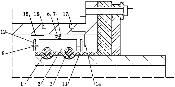
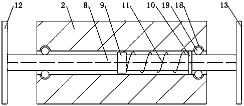
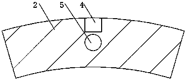
[0012] refer to Figure 1 to Figure 3 It can be seen that an electrical monitoring mechanism for the flow rate of a rotary compensator pipeline includes a clamp 1, the clamp 1 clamps the sealing sleeve on the outer wall of the inner tube, and a fixed block 2 is placed in the cavity between the inner tube and the outer tube. The lower side of the fixed block 2 is provided with a channel 3 symmetrically, the channel 3 fits with the clamp 1, the middle part of the fixed block 2 is provided with a telescopic rod cavity 4, and the fixed block 2 is located under the telescopic rod cavity 4 and runs throu...


PUM


Abstract

The invention relates to a rotary compensator pipeline flow speed electrical monitoring mechanism. The mechanism comprises a clamp. The clamp fixedly clamps a sealing sleeve on the outer side wall ofan inner pipe. A fixed block is arranged in a cavity between the inner pipe and an outer cylinder. Groove channels are symmetrically arranged in lower side face of the fixed block fits the clamp. A telescopic rod cavity is arranged in the middle part of the fixed block. A through groove is arranged in the lower part, in the telescopic rod cavity, of the fixed block. The through groove is perpendicular to the telescopic rod cavity. An inner rod is installed in the telescopic rod cavity. The upper end of the inner rod is fixedly connected with the inner side wall of the outer cylinder. A first spring sleeves the rod body, on the outer part of the fixed block, of the inner rod. According to the invention, the mechanism is proper in structure and convenient to use; the fixed block is installedon the clamp of the inner pipe of the current compensator; by use of the wind speed or the flow speed in the pipeline, the cross rod is allowed to move so as to allow a second metal plate to contacta third metal plate to allow the current to pass to make an alarm to give out sound, so it is convenient to carry out safety monitoring in the pipeline; and the monitoring cost is low.

Description

technical field [0001] The invention relates to the field of compensators, in particular to an electrical monitoring mechanism for flow velocity of a rotary compensator pipeline. Background technique [0002] Compensators are also customarily called expansion joints, or expansion joints. It consists of a bellows (an elastic element) that constitutes its main body and accessories such as end pipes, brackets, flanges, and conduits. Belongs to a compensation element. Utilize the effective expansion and contraction deformation of the bellows of its working body to absorb the dimensional changes of pipelines, conduits, containers, etc. caused by thermal expansion and contraction, or compensate the axial, lateral and angular displacement of pipelines, conduits, containers, etc. [0003] Some existing rotary compensators use clamps to fix the sealing sleeve for better sealing performance, but there is no safety monitoring device inside, which makes it inconvenient for workers to ...

Claims


Application Information

Patent Timeline
Patent Type & Authority Applications(China)
IPC IPC(8): G01P5/02
CPCG01P5/02
Inventor 朱海军
Owner 朱海军
Why Eureka
Try Eureka