
Metal rotary-cut button placement die

A mold and hardware technology, applied in the field of hardware rotary cutting processing equipment, can solve the problems of no waste cleaning, inconvenient treatment of ring workpiece burrs, etc., and achieve the effect of easy removal and reduced vibration

Inactive Publication Date: 2018-09-21
FOSHAN KUIFENG BUSINESS CONSULTATION SERVICES CO LTD
View PDF0 Cites 0 Cited by
  • Summary
  • Abstract
  • Description
  • Claims
  • Application Information

AI Technical Summary

Problems solved by technology

[0004] The purpose of the present invention is to provide a metal rotary cutting buckle mold to solve the problem of inconvenient handling of the burr of the ring-shaped workpiece in the above background technology, and at the same time not to clean up the waste after trimming

Method used


Image

  • Metal rotary-cut button placement die
  • Metal rotary-cut button placement die

Examples


Embodiment Construction

[0015] The following will clearly and completely describe the technical solutions in the embodiments of the present invention with reference to the accompanying drawings in the embodiments of the present invention. Obviously, the described embodiments are only some, not all, embodiments of the present invention. Based on the embodiments of the present invention, all other embodiments obtained by persons of ordinary skill in the art without making creative efforts belong to the protection scope of the present invention.

[0016] In describing the present invention, it should be understood that the terms "upper", "lower", "front", "rear", "left", "right", "top", "bottom", "inner", " The orientation or positional relationship indicated by "outside", etc. is based on the orientation or positional relationship shown in the drawings, and is only for the convenience of describing the present invention and simplifying the description, rather than indicating or implying that the referre...


PUM


Abstract

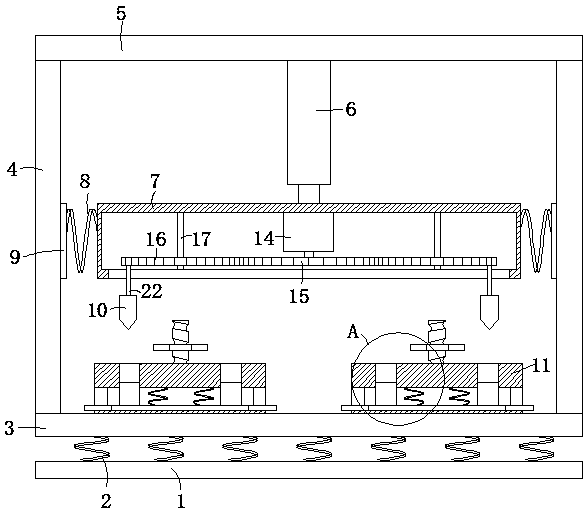
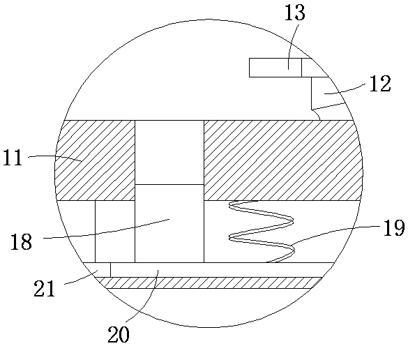
The invention discloses a metal rotary-cut button placement die which comprises a bottom plate, wherein a plurality of first damping springs are fixedly connected to the upper surface of the bottom plate, a horizontal plate is fixedly connected to one ends of the first damping springs, two supporting plates are fixedly connected to the upper surface of the horizontal plate, a top plate is fixedlyconnected between the two supporting plates, a hydraulic rod is fixedly connected to the lower surface of the top plate, a middle box is fixedly connected to the lower surface of the hydraulic rod, second springs are fixedly connected to the left end and the right end of the middle box, a sliding block is fixedly connected to one end of each second spring, the sliding blocks are in sliding connection to the lateral walls of the supporting plates, a plurality of rotary cutters are arranged on the lower side of the middle box, and the rotary cutters are transmitted by a transmission mechanism. The metal rotary-cut button placement die disclosed by the invention achieves treatment on burrs of annular work pieces; meanwhile, waste materials in a fixed block can be removed conveniently, and vibration during working is reduced; thus, the metal rotary-cut button placement die is worth of popularizing.

Description

technical field [0001] The invention relates to the technical field of hardware rotary cutting processing equipment, in particular to a hardware rotary cutting buckle mold. Background technique [0002] Many workpieces need to be trimmed after initial molding, especially stamped workpieces. However, the existing metal rotary cutting buckle molds are inconvenient to deal with the burrs of ring-shaped workpieces. At the same time, the waste after trimming is not cleaned up. When the vibration is relatively large, it affects the processing of the ring-shaped workpiece, so it brings inconvenience to the staff to handle the ring-shaped workpiece. [0003] Therefore, it is a problem we want to solve to provide a metal rotary cutting buckle mold that can solve the inconvenience of processing the burr of the ring workpiece and does not clean up the waste after trimming. Contents of the invention [0004] The object of the present invention is to provide a metal rotary cutting buc...

Claims


Application Information

Patent Timeline
Patent Type & Authority Applications(China)
IPC IPC(8): B23D79/00B23Q11/00
CPCB23D79/00B23Q11/0032B23Q11/0042
Inventor 王贵宝
Owner FOSHAN KUIFENG BUSINESS CONSULTATION SERVICES CO LTD
Learn More