Pneumatic lifting mechanism for laser cutter for sheet bars of heat exchanger and control method for pneumatic lifting mechanism

A laser cutting machine and heat exchanger technology, applied in the field of mechanical processing, can solve problems such as scratching the surface of heat exchanger plates, achieve the effect of increasing the pass rate and ensuring production quality

Pending Publication Date: 2018-09-21
辽宁光阳换热设备制造有限公司
View PDF10 Cites 1 Cited by
  • Summary
  • Abstract
  • Description
  • Claims
  • Application Information

AI Technical Summary

Problems solved by technology

The support platform composed of multiple support racks is used to prevent the laser cutting heat exchanger plate from scratching the support platform and solve the problem that the support platform composed of multiple support racks will scratch the surface of the heat exchanger plate

Method used


Image

  • Pneumatic lifting mechanism for laser cutter for sheet bars of heat exchanger and control method for pneumatic lifting mechanism
  • Pneumatic lifting mechanism for laser cutter for sheet bars of heat exchanger and control method for pneumatic lifting mechanism

Examples


Embodiment 1

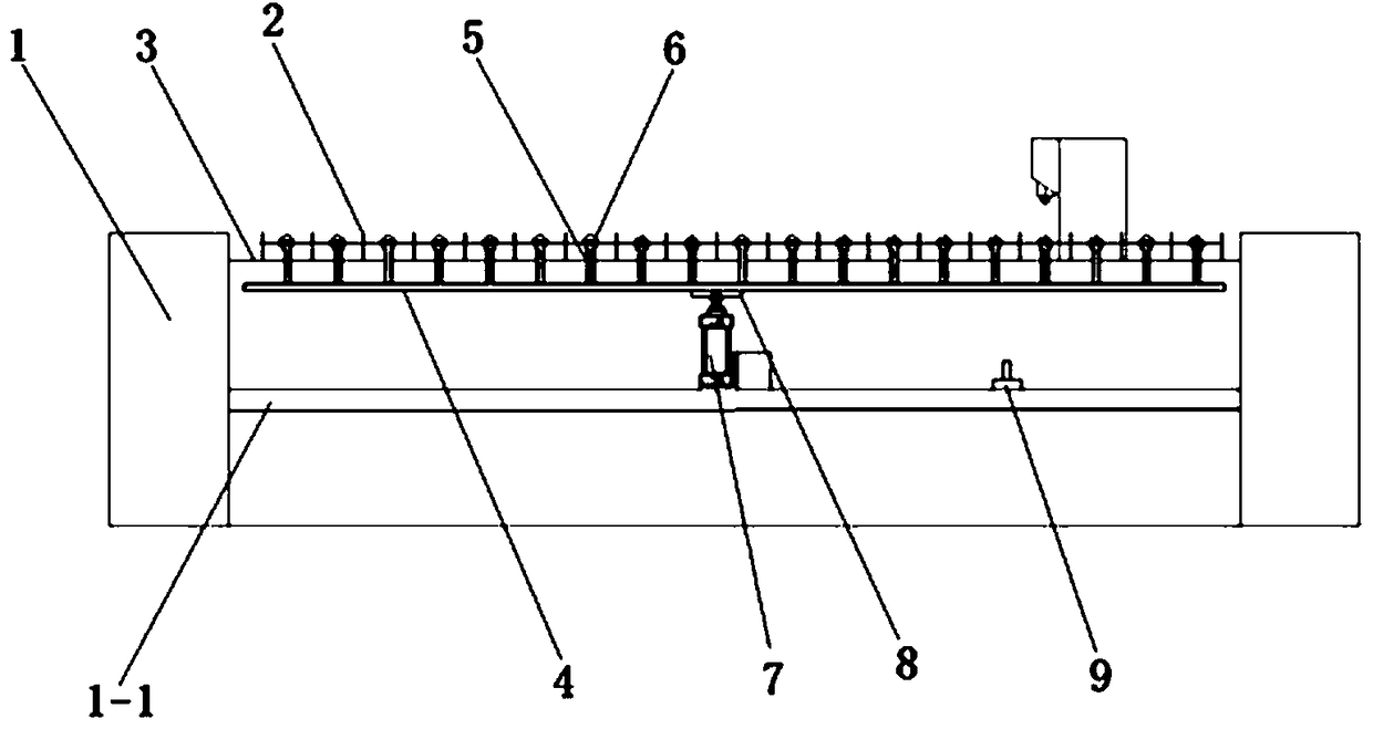
[0023] Embodiment 1, refer to figure 1 , the present invention includes: a bracket 1, a support platform 3 composed of a plurality of support racks 2, a pneumatic bracket 4, a pulley fixture 5, a pulley 6, and a cylinder assembly 7, wherein a plurality of support racks 2 are uniformly welded on the bracket On the side beam of 1, the shape of the supporting rack 2 is elongated, and the end of the supporting rack 2 close to the stainless steel sheet is uniformly provided with sawtooth-shaped teeth;

[0024] The cylinder assembly 7 is fastened on the beam 1-1 of the bracket 1 below the support platform 3 by bolts, and the top end of the piston rod protruding from the cylinder assembly 7 is fixedly connected with the bracket bottom plate 8, and the bracket bottom plate 8 is fastened to the pneumatic bracket by bolts. In the middle position of the frame 7, the cylinder assembly 7 drives the pneumatic bracket 4 to lift between the beam 1-1 of the bracket 1 and the support platform 3...

Embodiment 2

[0027] Embodiment 2, refer to figure 1 ,, The control method of the pneumatic lifting mechanism of the heat exchanger plate laser cutting machine includes the following steps:

[0028] Step S1: Use the cylinder assembly 7 to push the pneumatic bracket 4 up, and the pneumatic bracket 4 pushes out multiple sets of pulleys 6 from the gap between two adjacent support racks 2 in the support platform 3 through the pulley fixing member 5, All have pulley 6 to eject in every row's gap, utilize the far-infrared sensor 9 detection pulley 6 that is installed on the crossbeam 1-1 of supporting platform 3 lower supports 1 to be higher than the tooth that supports rack 2 tops, when pulley 6 When the height at this time was higher than the height of the 2 teeth of the support rack, the rising work of the cylinder assembly 7 stopped;

[0029]Step S2: When the height of the pulley 6 in step S1 is higher than the height of the teeth in the support rack 2, push the stainless steel sheet to the ...


PUM


Abstract

The invention discloses a pneumatic lifting mechanism for a laser cutter for sheet bars of a heat exchanger and a control method for the pneumatic lifting mechanism. The pneumatic lifting mechanism comprises a lifting platform which consists of a bracket and a plurality of lifting racks, a pneumatic bracket, slide wheel fixing parts, slide wheels and an air cylinder assembly, wherein the lifting platform is mounted on the bracket; the air cylinder assembly is mounted on a beam of the bracket below the lifting platform; the pneumatic bracket is mounted on an extending-out piston rod of the aircylinder assembly; the air cylinder assembly drives the pneumatic bracket to lift between the beam of the bracket and the lifting platform; a gap is formed between every two adjacent lifting racks inthe lifting platform; the slide wheels are uniformly distributed in the gap between every two adjacent lifting racks; the slide wheels are mounted on the slide wheel fixing parts through bearings or rotary shafts; and the slide wheel fixing parts are mounted on the pneumatic bracket. The pneumatic lifting mechanism has the advantages that the defect that laser cutter is used in a laser cutting production line for sheet bars of the heat exchanger is optimized, and guarantee is provided for large-scale production and industrial production.

Description

technical field [0001] The invention relates to the technical field of mechanical processing, in particular to a pneumatic lifting mechanism of a heat exchanger plate laser cutting machine and a control method thereof. Background technique [0002] The plate heat exchanger is a high-efficiency heat exchanger made up of a series of stainless steel plates. Thin rectangular channels are formed between various plates, and heat exchange is performed through the plates. Plate heat exchanger is an ideal equipment for liquid-liquid, liquid-vapor heat exchange. It has the characteristics of high heat exchange efficiency, small heat loss, compact and light structure, small footprint, wide application and long service life. In the case of the same pressure loss, its heat transfer coefficient is 3-5 times higher than that of the tube heat exchanger, and the floor area is one-third of that of the tube heat exchanger, and the heat recovery rate can be as high as 90%. [0003] At presen...

Claims


Application Information

Patent Timeline
Patent Type & Authority Applications(China)
IPC IPC(8): B23K26/70B23K26/38
CPCB23K26/38B23K26/702
Inventor 王春蒙朱德海
Owner 辽宁光阳换热设备制造有限公司
Why Eureka
Try Eureka