Eureka AIR delivers breakthrough ideas for toughest innovation challenges, trusted by R&D personnel around the world.

Mould structure

A mold and fixed template technology, applied in the field of mold structure, can solve the problems of molten rubber rushing into the cavity, high temperature, affecting product appearance, etc.

Pending Publication Date: 2018-09-21
WUHU MATY AIR CONDITIONING EQUIP CO LTD +1
View PDF0 Cites 4 Cited by
  • Summary
  • Abstract
  • Description
  • Claims
  • Application Information

AI Technical Summary

Problems solved by technology

[0002] At present, in the process of molding the air-conditioning panel with the etched surface through the mold, the outlet of the hot runner system is directly connected with the cavity, so that the molten rubber flowing out of the outlet of the hot nozzle of the hot runner system only needs to pass a short distance. It will flow into the cavity, which will cause the molten rubber to rush directly into the cavity, resulting in excessive injection pressure and high temperature. In this way, the molded product will have defects such as air marks and positive and negative surfaces on the outer surface, which will cause Affect the appearance of the molded product

Method used


Image

  • Mould structure
  • Mould structure
  • Mould structure

Examples


Embodiment Construction

[0046] In order to understand the above-mentioned purpose, features and advantages of the present invention more clearly, the present invention will be further described in detail below in conjunction with the accompanying drawings and specific embodiments. It should be noted that, in the case of no conflict, the embodiments of the present application and the features in the embodiments can be combined with each other.

[0047] In the following description, many specific details are set forth in order to fully understand the present invention. However, the present invention can also be implemented in other ways different from those described here. Therefore, the protection scope of the present invention is not limited by the specific details disclosed below. EXAMPLE LIMITATIONS.

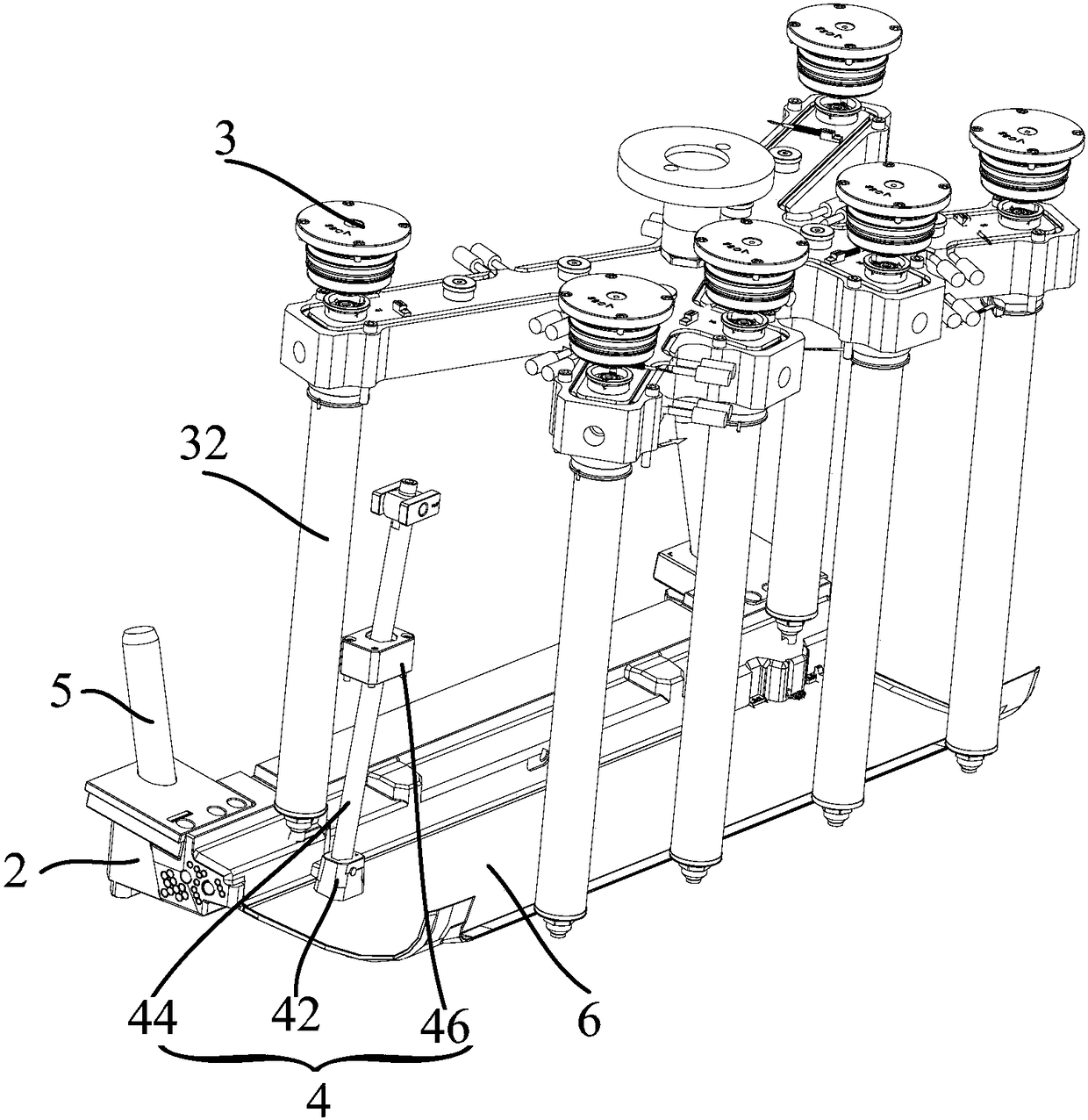
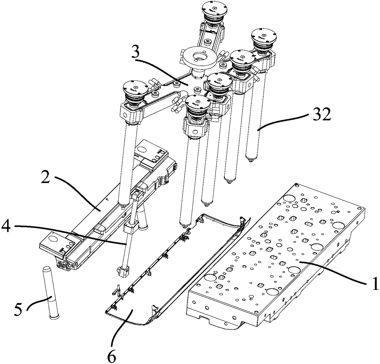
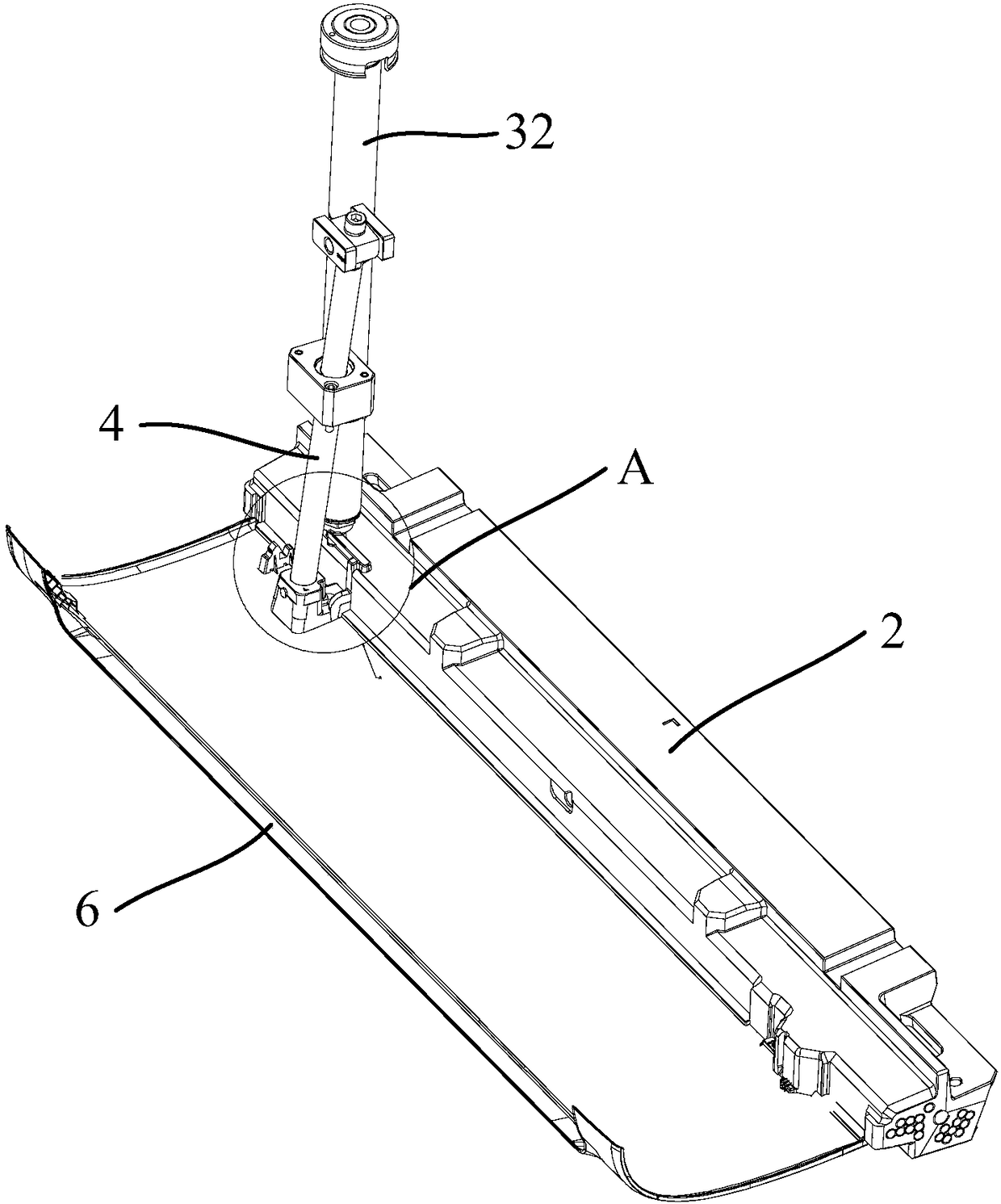
[0048] Refer below Figure 1 to Figure 6 The mold structure according to some embodiments of the present invention will be described.

[0049] Such as Figure 1 to Figure 6 As shown, the embodimen...


PUM


Abstract

The invention provides a mould structure, which is used for molding a workpiece. The mould structure comprises a fixed mould plate, a movable mould plate, a sliding block, a hot runner system and an inclined ejection assembly, wherein the movable mould plate is installed on the fixed mould, and a mold cavity is enclosed by the movable mould plate and the fixed mould plate; the sliding block is installed on the surface, close to the movable mould plate, of the fixed mould plate; the sliding block is provided with a first flow channel; the hot runner system comprises a hot sprue installed on thesliding block; an outlet of the hot sprue is communicated with the first flow channel; the inclined ejection assembly comprises an inclined ejection head; the inclined ejection head is installed in the mold cavity, is contacted with the side part of the sliding block, and can be used for ejecting the workpiece after a template component is subjected to mold opening; the inclined ejection head isprovided with a second flow channel communicated with the first flow channel and the mold cavity. According to the scheme, the sliding block is provided with the first flow channel, and the inclined ejection head is provided with the second flow channel, so that the communicating distance between an outlet of the hot sprue and the mold cavity is increased, and the pouring distance is further increased; the mould structure enables molten rubber to slowly enter the mold cavity, thus reducing the injection molding pressure and solving the problems that in the prior art, the surfaces of pattern etched surface products molded in the prior art are prone to defects such as gas lines and yin and yang sides.

Description

technical field [0001] The invention relates to the field of molds, in particular to a mold structure. Background technique [0002] At present, in the process of molding the air-conditioning panel with the etched surface through the mold, the outlet of the hot runner system is directly connected with the cavity, so that the molten rubber flowing out of the outlet of the hot nozzle of the hot runner system only needs to pass a short distance. It will flow into the cavity, which will cause the molten rubber to rush directly into the cavity, resulting in excessive injection pressure and high temperature. In this way, the molded product will have defects such as air marks and positive and negative surfaces on the outer surface, which will cause Affect the appearance of the molded product. [0003] Therefore, how to propose a mold structure capable of improving the quality of the outer surface of the molded product has become an urgent problem to be solved. Contents of the in...

Claims


Application Information

Patent Timeline
Patent Type & Authority Applications(China)
IPC IPC(8): B29C45/26B29C45/27B29C45/40
CPCB29C45/26B29C45/27B29C45/4005
Inventor 黎波廖广昆姚庆成陈庆高李健锋
Owner WUHU MATY AIR CONDITIONING EQUIP CO LTD
Why Eureka
Eureka Blog
Learn More