Lightning current shunt with self-locking device and mounting method

A technology of self-locking devices and shunts, applied in measuring devices, voltage/current isolation, instruments, etc., can solve problems such as scattered on floating plates, frequent extension and retraction, and elastic fatigue of planar scroll springs

Pending Publication Date: 2018-09-21
江苏驭雷安全科技有限公司
View PDF0 Cites 0 Cited by
  • Summary
  • Abstract
  • Description
  • Claims
  • Application Information

AI Technical Summary

Problems solved by technology

In actual use of this structure, when encountering strong winds, the copper braid is blown, resulting in frequent extension and retraction
Frequent stretching vibration will cause elastic fatigue or even fracture of the planar scroll spring in the equipment
Once the elastic force of the planar scroll spring becomes weaker or even broken, the braided belt cannot be retracted into the device and will be scattered on the floating plate

Method used


Image

  • Lightning current shunt with self-locking device and mounting method
  • Lightning current shunt with self-locking device and mounting method
  • Lightning current shunt with self-locking device and mounting method

Examples


Embodiment Construction

[0018] The present invention will be further described through specific embodiments below in conjunction with the accompanying drawings.

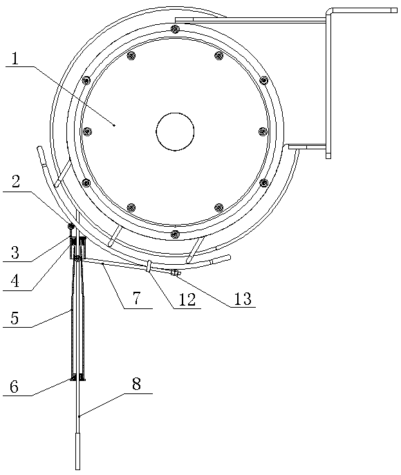
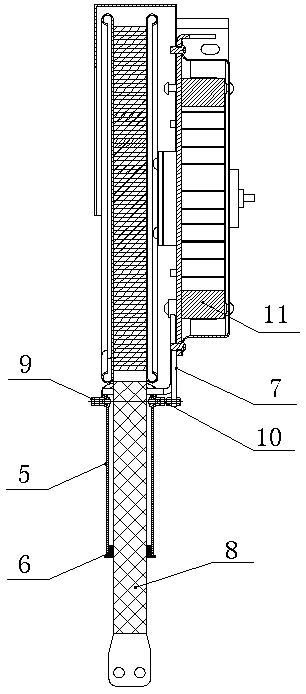
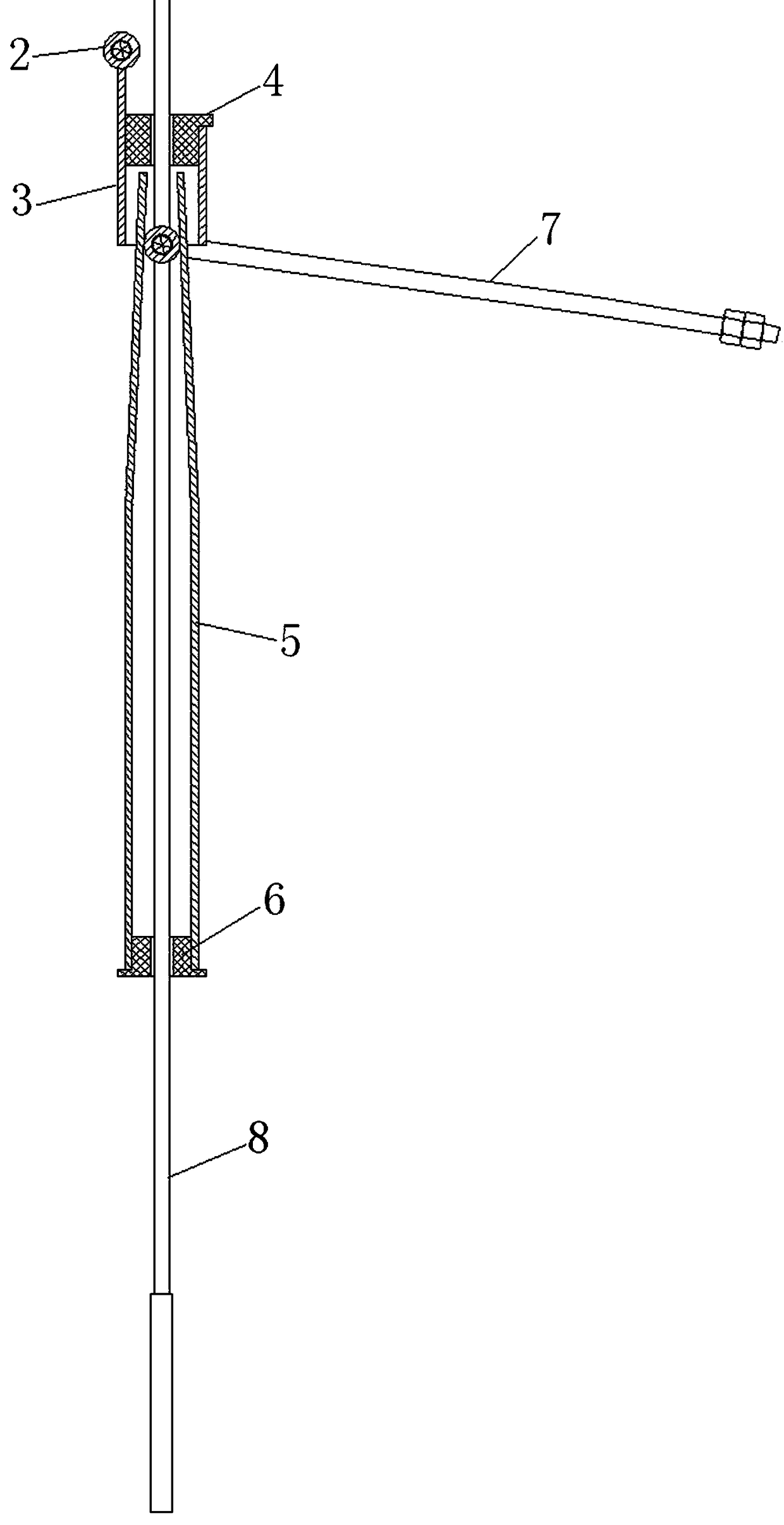
[0019] like figure 1 , figure 2 , image 3 As shown, a lightning current shunt with a self-locking device includes a lightning current shunt mechanism 1, a planar scroll spring 11 and a copper braid 8 inside the lightning current splitter mechanism 1, and one end of the planar scroll spring 11 is fixed On the shell of the lightning current shunt structure 1, the other end is fixed on the main shaft connected to the reel; one end of the copper braid 8 is fixed on the reel in the lightning current shunt structure 1, and the other end passes through The self-locking device fixed on the lightning current shunt structure 1, the self-locking device can give a reaction force to the copper braid 8 to be stretched in the swing state, reduce its stretching speed, and make the plane scroll spring 11 in a stable state .

[0020] The preferred solu...


PUM


Abstract

The invention discloses a lightning current shunt with a self-locking device. The lightning current shunt comprises a lightning current shunt mechanism, wherein a flat spiral spring and a copper wovenbelt are arranged in the lightning current shunt mechanism; one end of the flat spiral spring is fixed on a housing of a lightning current shunt structure, and the other end of the flat spiral springis fixed on a main shaft connected with a reel; one end of the copper woven belt is fixed to the interior of the reel in the lightning current shunt structure, and the other end of the copper woven belt passes through the self-locking device fixed on the lightning current shunt structure; and the self-locking device can exert a counter-acting force onto the copper woven belt which tends to stretch in a swinging state, so that the stretching speed of the copper woven belt is reduced, and the flat spiral spring is in a stable state. The lightning current shunt with the self-locking device is simple in structure and novel in design. The service life of the flat spiral spring is prolonged.

Description

technical field [0001] The invention belongs to a lightning current shunt, in particular to a lightning current shunt with a self-locking device. Background technique [0002] Large crude oil storage tanks are generally floating roof storage tanks, and the floating plate floats on the crude oil when in use. At present, in order to prevent crude oil vapor from leaking from the edge of the floating plate, it is usually sealed. This seal is completed by a non-conductive material, usually nitrile rubber, which can electrically insulate the floating plate from the tank wall. Make the floating disk an isolated conductor. Due to the high resistivity of crude oil, crude oil can generate a large amount of static charge when lightning occurs and crude oil is quickly filled into tanks, and these charges will gradually transfer to an attractive conductor with an opposite charge. The floating plate will collect the static charge of crude oil. The induced voltage of the static charge ca...

Claims


Application Information

Patent Timeline
IPC IPC(8): B65H75/44B65H75/48B65D90/46G01R15/14G01R11/02
CPCG01R11/02G01R15/146B65D90/46B65H75/4439B65H75/486
Inventor 徐艳田倩
Owner 江苏驭雷安全科技有限公司
Why Eureka
Try Eureka