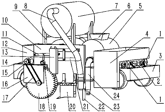
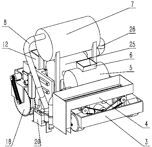
[0025] Example: such as Figure 1 to Figure 9 In the shown robot system for automatic paving of roadside stones, the technical solution adopted by the present invention is: a robot system for automatic paving of roadside stones, including a stone feeding part, a groove cutting part, and a foundation material recovery part.
[0026] The stone feeding part includes an L-shaped stone feeding bracket 4, a conveying motor 36, two supporting rods 30 and two eccentric disk shafts 31. The L-shaped stone feeding bracket 4 is fixedly installed at the rear of the car body 3, and the bottom surface of the L-shaped stone feeding bracket 4 Two rectangular through grooves are arranged perpendicular to the length direction of the car body 3, and two sets of mounting seats 401 are arranged on the outside of the bottom surface of the L-shaped stone feeding bracket 4, the axis of the mounting seat 401 is perpendicular to the length direction of the rectangular through groove, and two eccentric disc shafts 31 are respectively rotatably mounted on the mounting seat 401, two eccentric discs are eccentrically arranged on the circumference of the eccentric disc, and the axial directions of the two eccentric discs are coincident, the support rod 30 is provided with two rotating holes, two rotating holes The two supporting rods 30 are driven by the two eccentric disk shafts to move freely in the two rectangular through grooves on the bottom surface of the L-shaped stone feeding support 4, respectively. A timing belt wheel 1 is fixedly installed at the ends of the two eccentric disc shafts 31, the conveying motor 36 is fixedly installed on the car body 3, and is located under the L-shaped stone feeding bracket 4, and the output shaft of the conveying motor 36 is fixedly installed with a drive Synchronous belt wheel, the transmission between the synchronous belt wheel 1 and the active synchronous belt wheel is through the synchronous belt 2.
[0027] The cutting part is slidably installed on the left side of the car body 3, including the up and down moving cylinder 29, the cylinder body of the up and down moving cylinder 29 is hinged with the car body 3, the cylinder rod of the up and down moving cylinder 29 is hinged with the upper end of the cutting bracket 10, and the cutting bracket 10 A saw bracket 16 is provided at the lower left end, a motor 13 is installed on the left side of the upper surface of the saw bracket 16, a pulley 15 is installed on the output shaft of the motor 13, a saw shaft 34 is installed on the lower right of the saw bracket 16, and the outer end of the saw shaft 34 is installed The driven pulley 15, the pulley 15 and the driven pulley are driven by the belt 17; the right side of the upper surface of the saw support 16 is provided with a hydraulic motor 19, the output shaft of the hydraulic motor 19 is connected with the connecting rod through a crank, and the connecting rod is in the middle of the pressure rod 11. Hinged, the left end of the pressure rod 11 is hinged with the cutting support 10, and the right side of the pressure rod 11 is provided with a waist-shaped groove; the upper right of the cutting support 10 is provided with two hollow horizontal parallel connecting rods 21, the right end of the horizontal parallel connecting rod 21 is connected to the cutting support The bracket 10 is hinged, and the left end is provided with a vertical parallel link. The horizontal parallel link 21, the vertical parallel link and the cutting bracket 10 form a parallelogram structure. One of the upper and lower horizontal parallel links 21 is slidably installed along the axis direction. The telescopic connecting rod 35, the notch part also includes a breaking hammer 12 and a horizontal impact hammer 20. The breaking hammer 12 is provided with two rotating shafts 1302, and a pin 1301 is arranged between the two rotating shafts 1302. The upper and lower rotating shafts 1302 are respectively telescopic The left end of the connecting rod 35 is pivoted and hinged, and the pin 1301 slides in the waist-shaped groove on the pressing rod 11; the horizontal impact hammer 20 is installed on the lower side of the cutting bracket 10.
[0028] The foundation material recovery part includes a separator 7. The separator 7 has a cylindrical structure and is fixed on the separator bracket 9. The separator bracket 9 is installed in the middle of the car body 3. One end of the separator 7 is provided with a separator input pipe 8 for separating The end of the machine input pipe 8 is provided with a partition 22; the separator 7 communicates with the pulverizer 25 through a connecting pipe 26.
[0029] A slide frame 28 is provided between the cutting bracket 10 and the vehicle body 3. Two vertical slide frames 28 are provided in parallel, and the slide frame 28 is fixed on the vehicle body 3 on one side; the cutting bracket 10 is provided with two vertical The straight dovetail body is respectively matched with the dovetail groove provided on the slide frame 28, and the cutting bracket 10 slides up and down in the dovetail groove of the slide frame 28.
[0030] The lower end of the L-shaped stone feeding support 4 is provided with an opening on the side close to the car body. The opening is provided with a baffle 33 which is rotatably connected with the rotating shaft at the upper part of the opening. A rotation control arm is also provided outside the baffle 33 to rotate. The end of the control arm is hinged with the cylinder rod of the cylinder 32, and the cylinder body of the cylinder 32 is hinged to the left side of the bottom of the L-shaped rock feeding support 4 through the cylinder mounting seat. The saw shaft 34 is a stepped shaft, and a saw blade 18 is fixedly mounted on the journal of the stepped shaft. The breaking hammer 13 is arranged behind the saw support 16 and between the two saw blades 18; the horizontal impact hammer 20 is directly behind the breaking hammer 13 and the saw blade 18, and the impact hammer is provided with an inlet and an outlet. Crusher, and the lowest end of the impact hammer and the lowest end of the saw blade 18 are on the same horizontal line. The pulverizer 25 communicates with the stirring pump 5 through the connecting pipe 26. The upper end of the stirring pump 5 is provided with an upper silo 6 and the left side is provided with an output duct 24 of the stirring pump. The end of the output duct 24 of the stirring pump is vertical. The mortar sprayer 23 is straightly arranged. The mortar sprayer 23 has a rectangular structure, and the length of the rectangular structure is equal to the distance between the two saw blades 18. The mortar sprayer 23 is directly behind the input end of the separator input pipe 8 . The input end of the separator input pipe 8 is fixed by a fixing frame 27 and is located directly behind the outlet of the horizontal impact hammer 20. The fixing frame 27 is fixed at the lower right of the cutting bracket 10. A compression spring is installed between the inner right end of the horizontal parallel link 21 and the telescopic link 35.
[0031] In the working process of the present invention adopting the above-mentioned embodiments, first, the saw blade 18 is driven by the motor 14 to rotate at a high speed, and the groove is cut at the position where the curbstone is to be laid, and the breaker 13 hammers the sawed strip roadbed material The horizontal impact hammer 20 horizontally separates the roadbed material at the bottom of the trench, and finally determines the depth of the trench. The broken roadbed material is initially crushed by the crusher to a granular shape that can be sucked by the separator 7. The separator 7 Inhale and separate the roadbed materials in the grooves, separate the soft materials with lower hardness than the standard, and discharge them into the waste bin 12. The separated reused materials enter the pulverizer 25 through the conduit for pulverization, and meet the requirements of cement mortar. The material crushed by the pulverizer 25 is sent to the mixing pump 5, while the mixing pump 5 is filled with water, cement and other materials for mixing, and the mixed mortar is pumped by the mixing pump 5 In the opened groove, the L-shaped stone feeding bracket 4 puts the prefabricated curb stone into a predetermined position, and uses an oscillator to oscillate and hammer into place.