
Diesel engine monitor with temperature measuring function

A diesel engine and monitor technology, which is applied in mechanical equipment, engine components, machines/engines, etc., can solve the problems of increased economic investment of users, unfavorable use of monitors, user injuries, etc., and achieves simple structure and improved use. Lifespan, damage reduction effect

Inactive Publication Date: 2018-09-21
JIANGSU MARITIME INST
View PDF0 Cites 0 Cited by
  • Summary
  • Abstract
  • Description
  • Claims
  • Application Information

AI Technical Summary

Problems solved by technology

[0002] Diesel engine is a machine that burns diesel to obtain energy release. The advantages of diesel engine in energy saving and carbon dioxide emission cannot be replaced by all heat engines including gasoline engine. Some advanced small high-speed diesel engines, due to their good comprehensiveness, It is more and more widely used: the existing diesel engine has certain disadvantages when it is used. First, due to the characteristics of the diesel engine itself, it will release a lot of heat during the working process. Under normal circumstances, it will cause serious injury to the user. Secondly, due to the inevitable vibration during the use of the diesel engine, it is likely to cause the monitor to fall, which is not conducive to the use of the monitor. In addition, because the monitor is only used in the diesel engine It only plays a role in the process, so the special configuration of a separate monitor for the diesel engine increases the unnecessary economic investment of the user, and is not conducive to people's use, and has a certain impact on the people's use process. Therefore, we propose a A Diesel Engine Monitoring Instrument Measuring Temperature

Method used


Image

  • Diesel engine monitor with temperature measuring function
  • Diesel engine monitor with temperature measuring function
  • Diesel engine monitor with temperature measuring function

Examples


Embodiment Construction

[0016] In order to make the technical means, creative features, objectives and effects of the present invention easy to understand, the present invention will be further explained below in conjunction with specific embodiments.

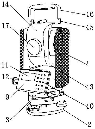
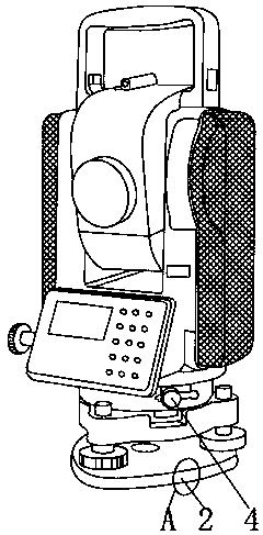
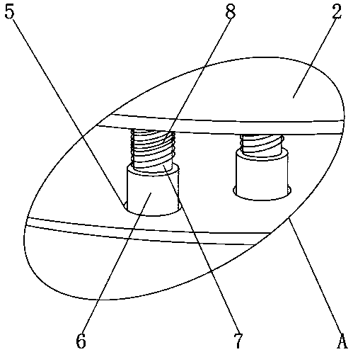
[0017] Such as Figure 1 to 4 As shown, a temperature-measurable diesel engine monitor of the present invention includes a body shell 1, a spring 8, a display 9 and a jack 19. The outer surface of the lower end of the body shell 1 is fixedly mounted with a base 2, and the base 2 The base locking knob 3 and the height adjusting knob 4 are fixedly installed on the outer surface of the upper end. The base locking knob 3 is located on one side of the height adjusting knob 4, and the base 2 is provided with a groove 5 and the inside of the groove 5 A sleeve 6 is fixedly installed. A telescopic shaft 7 is fixedly installed on the outer surface of the upper end of the sleeve 6, a spring 8 surrounds the outer surface of the telescopic shaft 7, a display 9 is fix...


PUM


Abstract

The invention discloses a diesel engine monitor with a temperature measuring function. The diesel engine monitor comprises a machine body shell, a spring, a display and an inserting hole, a base is fixedly arranged on the outer surface of the lower end of the machine body shell, a base locking knob and a height adjusting knob are fixedly arranged on the outer surface of the upper end of the base,the base locking knob is located on one side of the height adjusting knob, a groove is formed inside the base, a sleeve is fixedly arranged inside the groove, the outer surface of the upper end of thesleeve is fixedly provided with a telescopic shaft, the spring is arranged on the outer surface of the telescopic shaft in a surrounding mode, and the display is fixedly arranged on the outer surfaceof one side of the machine body shell. According to the monitor, a scanner, a damping layer and a plug bolt are arranged, so that different temperatures of different positions of a diesel engine canbe displayed, the damage of the impact force to the monitor can be weakened, the monitor also can be conveniently fixed or moved, and a better application prospect is brought.

Description

Technical field [0001] The invention relates to the technical field of diesel engine equipment, in particular to a diesel engine monitoring instrument capable of measuring temperature. Background technique [0002] Diesel engines are machines that burn diesel oil to obtain energy release. The advantages of diesel engines in terms of energy saving and carbon dioxide emissions cannot be replaced by all heat engines, including gasoline engines. Some advanced small high-speed diesel engines, due to their good comprehensiveness, More and more widely used: Existing diesel engines have certain drawbacks when in use. First, due to the characteristics of diesel engines, they will release a lot of heat during operation, which can be unknowingly or accidentally Under the circumstances, it will cause serious injury to the user. Secondly, due to the inevitable vibration during the use of the diesel engine, the monitor is likely to fall, which is not conducive to the use of the monitor. In ad...

Claims


Application Information

Patent Timeline
IPC IPC(8): F02B77/08
CPCF02B77/08F02B77/089
Inventor 张英华周国华赵云博
Owner JIANGSU MARITIME INST
Learn More