Linear motion bearing

A linear motion bearing and bearing outer ring technology, applied in the direction of linear motion bearings, bearings, shafts and bearings, can solve the problems of increased installation cost, no positioning structure, time-consuming and labor-intensive, etc., to reduce occupied space and installation. cost effect

Active Publication Date: 2018-09-21
宁波美亚特精密传动部件有限公司
View PDF6 Cites 1 Cited by
  • Summary
  • Abstract
  • Description
  • Claims
  • Application Information

AI Technical Summary

Problems solved by technology

[0003] At present, most linear bearings do not have a positioning structure, but are directly installed on the guide shaft. When an object needs to be positioned, a positioning device is often installed on the equipment, which is time-consuming and laborious, and increases the installation cost. Therefore, the existing There is still room for improvement in linear motion bearings

Method used


Image

  • Linear motion bearing
  • Linear motion bearing
  • Linear motion bearing

Examples


Embodiment Construction

[0033] The present invention will be described in further detail below in conjunction with the accompanying drawings.

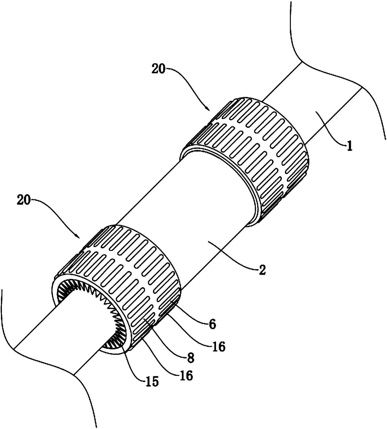
[0034] A linear motion bearing disclosed in this embodiment, such as figure 1 As shown, it includes a bearing outer ring 2 for the guide shaft 1 to slide and pass through. A retainer 17 is installed in the bearing outer ring 2 for the guide shaft 1 to pass through. The retainer 17 is equipped with a plurality of steel balls 18, and is used as Infinite circular movement enables the guide shaft 1 to slide smoothly in the cage 17 , so that the bearing outer ring 2 can slide along the guide shaft 1 .

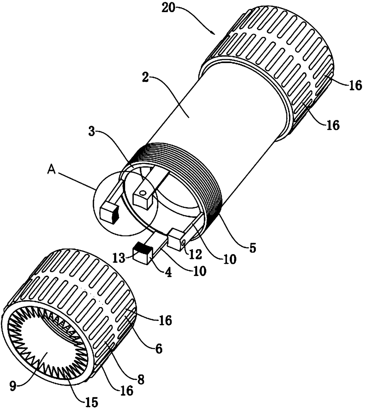
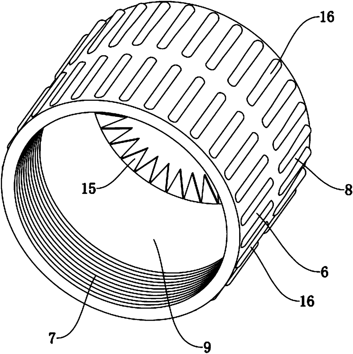
[0035] Such as figure 1 with figure 2 As shown, the end of the bearing outer ring 2 is provided with a positioning mechanism 20, and the positioning mechanism 20 is provided with two groups, which are symmetrically arranged at both ends of the bearing outer ring 2 respectively. Each set of positioning mechanisms 20 includes an engaging sleeve 3, several positio...


PUM


Abstract

The invention discloses a linear motion bearing with an aim to solve the problem that a positioning device is additionally arranged on an existing linear bearing costs high. The technical scheme includes that a positioning mechanism is arranged on the end face of a bearing outer ring and comprises a connecting sleeve fixed onto the end face of the bearing outer ring and extending outwards, a plurality of positioning blocks connected to the end face of the connecting sleeve and annularly arranged on a guiding shaft and a locking assembly abutted against end faces of the positioning blocks and away from the guiding shaft to force the positioning blocks to press the peripheral surface of the guiding shaft. The peripheral surface of the guiding shaft is pressed through the locking assembly, the body of the guiding shaft can be firmly clamped through the end face of the bearing outer ring, the axial position of the entire linear motion bearing on the guiding shaft can be effectively limited, external positioning structure is not needed, mounting cost is greatly reduced, and meanwhile, occupy space is reduced.

Description

technical field [0001] The invention relates to a bearing mechanism, in particular to a linear motion bearing. Background technique [0002] Linear motion bearings are low-cost produced linear motion systems for infinite travel in conjunction with guide shafts. The structure of the linear bearing is that a retainer is installed inside the outer ring, and the retainer is equipped with a plurality of steel balls, and performs infinite circular motion. The two ends of the retainer are fixed by internal spring retaining rings, and there is a gap window on the side of the linear track where each steel ball works under force. This part is to make the loaded steel ball and the guide shaft make rolling contact and relatively move with a very low friction coefficient. Therefore, linear motion bearings are the most suitable bearings for mechanical equipment, automation equipment, and energy-saving equipment. [0003] At present, most linear bearings do not have a positioning structu...

Claims


Application Information

Patent Timeline
Patent Type & Authority Applications(China)
IPC IPC(8): F16C29/04F16C29/10
CPCF16C29/04F16C29/10
Inventor 王民豪
Owner 宁波美亚特精密传动部件有限公司
Why Eureka
Try Eureka