Air heater for foam plastic production

An air heater and foamed plastic technology, which is applied to heat storage heaters, fluid heaters, lighting and heating equipment, etc., can solve the problems of unsatisfactory effect, difficult air temperature, and complicated operation, and achieves low production cost and high efficiency. The effect of high-quality production and efficient heat exchange

Inactive Publication Date: 2018-09-21
高密市美佳硕机械科技有限公司
View PDF0 Cites 0 Cited by
  • Summary
  • Abstract
  • Description
  • Claims
  • Application Information

AI Technical Summary

Problems solved by technology

[0003] The following problems exist in the prior art. Air at room temperature is used in the air transportation pipeline. When using room temperature air to blow EPS raw material particles into the mold cavity of the foam plastic mold, the room temperature air will quickly reduce the temperature of the foam plastic mold. , so that in the subsequent process of using high-temperature steam to heat the foam plastic mold, more heat will be consumed to heat the foam plastic mold to the target temperature, and the heating process will also take longer, which will make the EPS in the foam plastic mold The foaming effect of the raw material particles is poor, causing the surface of the foam plastic product to be rough, which seriously affects the quality of the foam plastic product. A patent for an energy-saving heat exchanger for foam plastic production (authorized announcement number: 206633302) proposes the use of The method of heating the air in the air duct with the high-temperature water generated after the foam plastic mold increases the temperature of the air in the air duct. Due to the limitation of the water temperature, the range of the air temperature raised by this method is low and the speed is slow, which is difficult to meet the requirements of the future. The effect of rapid temperature rise of EPS raw material particles is not ideal; and in the production process of foam plastic molds, due to the large changes in the external temperature of the four seasons, the existing equipment needs to adjust the temperature control equipment in different seasons, and the operation is cumbersome. Moreover, the air temperature in the air transportation pipeline is also difficult to control within an appropriate range

Method used


Image

  • Air heater for foam plastic production
  • Air heater for foam plastic production
  • Air heater for foam plastic production

Examples


Embodiment Construction

[0018] In order to facilitate the understanding of those skilled in the art, the present invention will be further described below in conjunction with the accompanying drawings.

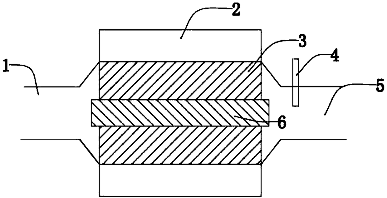
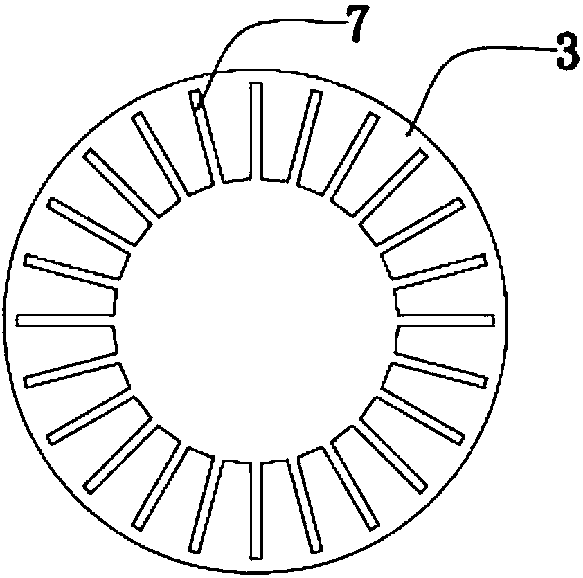
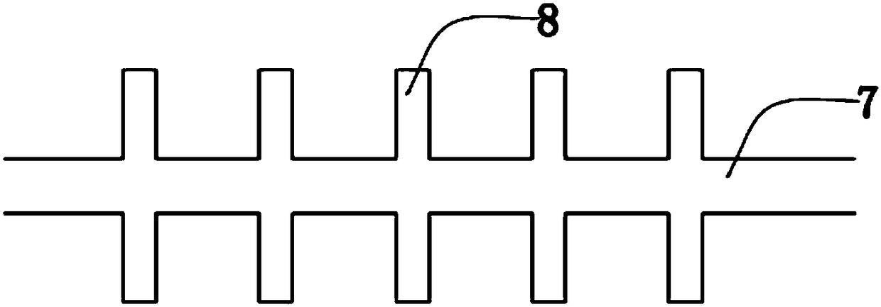
[0019] Such as Figure 1-3 As shown, the present invention includes a hollow pipe body 3, the two ends of the pipe body 3 are respectively connected with an air inlet 1 and an air outlet 5, the pipe body 3 is made of pure copper, and the inner wall of the pipe body 3 is provided with a number of axial The heat exchange tank 7, the pipe body 3 is also provided with a retaining column 6 to fill the hollow area of ​​the pipe body 3, the outer wall of the pipe body 3 is provided with a heating device 2, and the air outlet 5 is provided with a temperature detection device 4; The grooves 7 are evenly distributed on the inner wall of the pipe body 3 , and the heat exchange grooves 7 are provided with a plurality of tooth grooves 8 along the axial direction of the pipe body 3 .

[0020] Concrete mode of wor...


PUM


Abstract

The invention discloses an air heater for foam plastic production, and belongs to the technical field of air heating devices. The air heater comprises a hollow tube body, the two ends of the tube bodycorrespondingly communicate with an air inlet and an air outlet, the tube body is made of pure copper, and a plurality of axial heat exchange grooves are formed in the inner wall of the tube body; and a blocking column is further arranged in the tube body to fill the hollow area of the tube body, a heating device is arranged on the outer wall of the tube body, and a temperature detection device is arranged at the air outlet. According to the air heater, heat generated by the external heating device can be rapidly transferred to the interior of the tube body through the tube body with the purecopper material, air can be fully contacted with the inner wall of the tube body through the heat exchange grooves, so that high-efficiency heat exchange is achieved, and the air is guaranteed to beheated to a preset temperature in a short time.

Description

technical field [0001] The invention relates to the technical field of air heating devices, in particular to an air heater used in the production of foamed plastics. Background technique [0002] Foamed plastic products have the characteristics of light weight and good shock resistance, and are widely used in the packaging of disappearing molds, medical care, food, electromechanical, instrumentation, hardware and daily products. The foamed plastic products are made of EPS (expandable polystyrene) Raw pellets are made. The existing processing method of foamed plastics is: put the EPS raw material particles into the mold cavity of the foamed plastic mold by air transportation, heat the foamed plastic mold by high-temperature steam to make the EPS raw material particles foam, and after the foaming is completed, use cooling water to Cooling the foam mold separates the foam article from the foam mold. [0003] The following problems exist in the prior art. Air at room temperatu...

Claims


Application Information

Patent Timeline
Patent Type & Authority Applications(China)
IPC IPC(8): F24H7/02F24H9/20
CPCF24H7/0216F24H9/2078
Inventor 刘宝清
Owner 高密市美佳硕机械科技有限公司
Why Eureka
Try Eureka