Pipe airtightness detecting worktable,

An air tightness detection and workbench technology, which is used in fluid tightness testing, liquid tightness measurement using liquid/vacuum degree, and testing of machine/structural components, etc. , qualitative can not be quantitative and other problems, to reduce the detection time, enhance the degree of automation, improve labor efficiency

Active Publication Date: 2018-09-21
武汉金福汽配有限公司
View PDF15 Cites 11 Cited by
  • Summary
  • Abstract
  • Description
  • Claims
  • Application Information

AI Technical Summary

Problems solved by technology

Disadvantages: the method is primitive, the workload is heavy, it can only be qualitative but not quantitative, and the inspection effect is not ideal
(2) Air leak detectors, mostly manual testing
Disadvantages: manual inspection can only work on a single piece flow, and it is difficult to deal with the inspection of a large number of products
[0003] The common point of the above two technical solutions is that the structure is complicated. Although the technical solution with the application publication number of CN 105067197 A realizes the automatic air tightness detection of the pipe fittings in the water tank, it is not suitable for special pipe fittings for water detection; authorized announcement The technical solution with the number CN 205038030 U will produce insufficient negative pressure to affect the effect and accuracy of the detection. The structure of the plugging mechanism is relatively complicated, mainly because the air pressure in the cylinder is reduced, and the piston rod is retracted and compressed, so that the flexible sealing ring arches and expands. It seals the pipe fittings, but the cylinder itself has poor sealing performance and is prone to external leakage, which leads to the instability of the entire plug mechanism and affects the detection results

Method used


Image

  • Pipe airtightness detecting worktable,
  • Pipe airtightness detecting worktable,
  • Pipe airtightness detecting worktable,

Examples


Embodiment 1

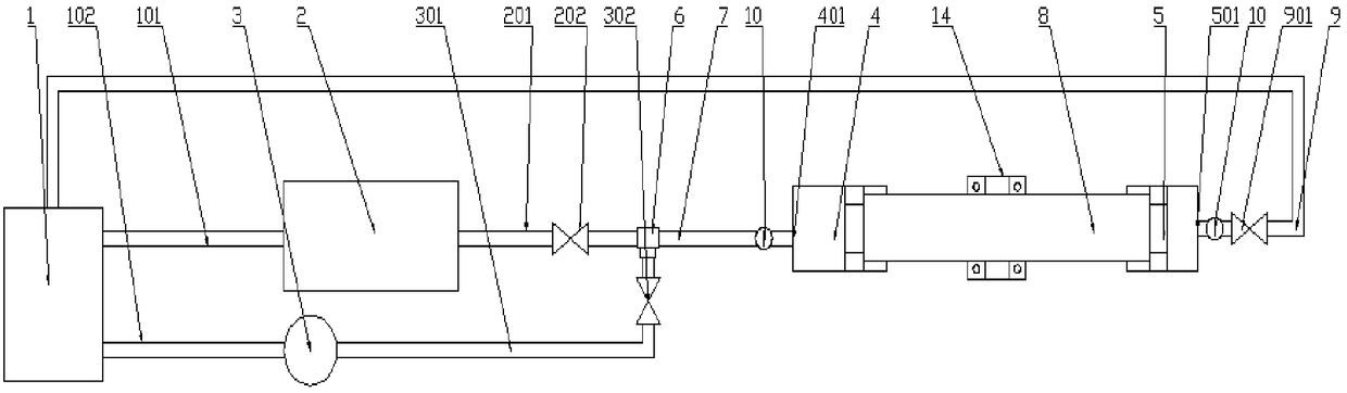
[0035] like Figure 1-2 As shown, a pipe fittings airtightness detection workbench includes an inflation device 1, a high-pressure auxiliary tank 2, a detection device 3, a first pipe fittings airtight pressurization positioning device 4, a second pipe fittings airtight pressurization positioning device 5; The inflation device 1 is connected to the detection device 3 through the first air inlet pipe 101, and the detection device 3 is also provided with a first air outlet pipe 301; the high-pressure auxiliary tank 2 is connected to the inflation device through the second inlet pipe 102. 1 connection; the high-pressure auxiliary tank 2 is also provided with a second air outlet pipe 201, and the first air outlet pipe 301 and the second air outlet pipe 201 communicate with the main air intake pipe 7 through a tee 6; The trachea 7 is connected to the first pipe airtight pressure positioning device 4, the other end of the first pipe airtight pressure positioning device 4 is connecte...

Embodiment 2

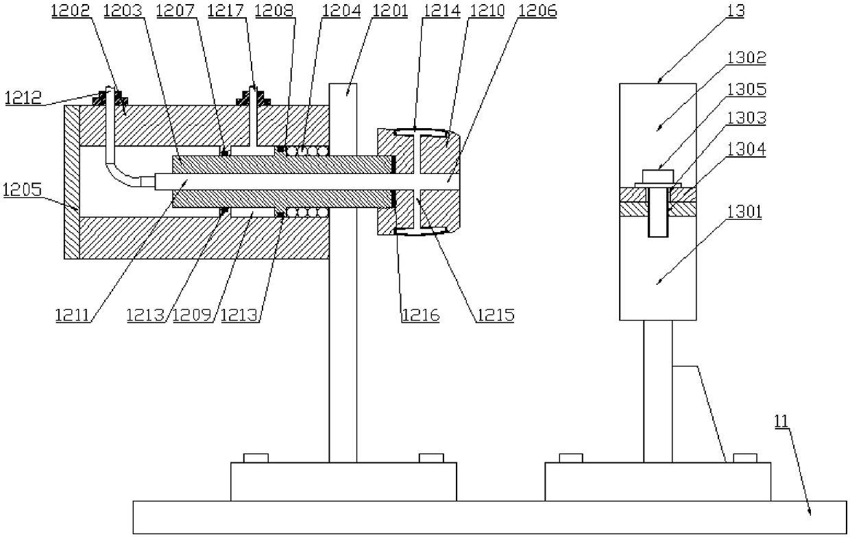
[0039] like image 3 As shown, a pipe fittings airtightness detection workbench, this embodiment is similar to the structure principle of the embodiment, and the difference from Embodiment 1 is that the first pipe fittings airtight pressurization positioning device 4 and the second The airtight pressurization and positioning devices 5 of the two pipe fittings all include a base 11 and a pneumatic pressurization mechanism 12 fixedly installed on the base 11. The pneumatic pressurization mechanism 12 includes a bracket 1201, a cylinder liner 1202, a push rod 1203, and a spring 1204. And the rear cover plate 1205, the cylinder liner 1202 is installed on the bracket 1201; the cylinder liner 1202 is a through-hole structure, and the inner cavity of the through hole is provided with a sealing guide ring 1207; the inner sleeve of the cylinder liner 1202 There is a push rod 1203, the push rod 1203 is provided with a sealing shoulder 1208, the sealing guide ring 1207 and the sealing sh...

Embodiment 3

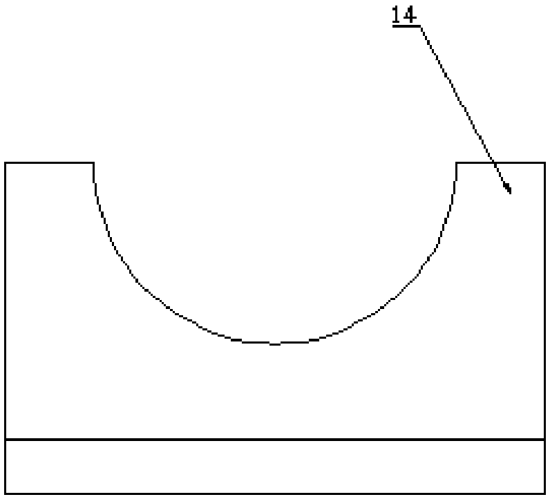
[0046] like Figure 4 As shown, a pipe fittings air tightness detection workbench, this embodiment is similar to the structure principle of embodiment 1 and embodiment 2, the difference between this embodiment and embodiment 1 and embodiment 2 is that the base 11 is also A pipe fitting fixing seat 13 is provided, and the pipe fitting fixing seat 13 includes a U-shaped base 1301 and a U-shaped cover 1302, the U-shaped cover 1302 is hinged and fixed on the U-shaped base 1301, and the U-shaped cover 1302 A through hole 1303 is provided on the movable end of the U-shaped base 1301, and a threaded hole 1304 matching the through hole 1303 is correspondingly provided on the U-shaped base 1301, and the U-shaped cover plate 1302 is fixed on the On the U-shaped base 1301 ; the U-shaped bottom of the U-shaped base 1301 and the U-shaped cover 1302 are respectively provided with anti-slip pads 1306 .


PUM


Abstract

The invention discloses a pipe airtightness detecting worktable. The worktable comprises an inflation device, a high-pressure auxiliary tank, a detecting device, a first pipe member airtight pressurepositioning device, and a second pipe member airtight pressure positioning device; the detecting device is provided with a first air outlet pipe; the high pressure auxiliary tank is connected to the airing device through a second air inlet pipe; the high-pressure auxiliary tank is further provided with a second air outlet pipe, and the first air outlet pipe and the second air outlet pipe are connected to the main air intake pipe through a three-way pipe; the main intake pipe is connected to the first pipe member airtight pressure positioning device, and the other end of the first pipe member airtight pressure positioning device is connected with a pipe member. The other end of the pipe member is connected with the second pipe member airtight pressure positioning device, and the other end of the second pipe member airtight pressure positioning device is connected with a main air outlet pipe; the worktable controls the high-pressure auxiliary tank and the detecting device to pressurize the pipe member through the electromagnetic valve, thereby reducing the time for detecting the pipe fitting and improving the working efficiency.

Description

technical field [0001] The invention relates to the technical field of pipe fitting performance testing equipment manufacturing, in particular to a pipe fitting air tightness testing workbench. Background technique [0002] In the production of automobile air intake pipes, the air intake pipes are welded by multiple pipe bodies and bases. Leakage points are prone to occur at the pipe body welds and are difficult to find, or they are burned through during welding, so air tightness testing is required. At present, the air tightness test of pipe fittings is as follows: (1) There is no instrument, and water test is used. Workers use rubber tubes to connect the two ends of the pipe fittings, put the pipe fittings into the water, and observe the leakage situation. When there are bubbles coming out, it is judged as a substandard product. Disadvantages: The method is primitive, the workload is heavy, it can only be qualitative but not quantitative, and the inspection effect is not ...

Claims


Application Information

Patent Timeline
Patent Type & Authority Applications(China)
IPC IPC(8): G01M3/28
CPCG01M3/2815
Inventor 郭文广陈雅
Owner 武汉金福汽配有限公司
Why Eureka
Try Eureka