Card reading method, payment terminal (POS, Point Of Sale) and terminal equipment

A payment terminal and card reading technology, which is applied in payment architecture, hybrid readers, instruments, etc., can solve the problems of program developers, increase the difficulty of card reader program development, and limited space in the card reading area.

Active Publication Date: 2018-09-21
PAX COMP TECH SHENZHEN
View PDF4 Cites 6 Cited by
  • Summary
  • Abstract
  • Description
  • Claims
  • Application Information

AI Technical Summary

Problems solved by technology

[0004] In view of this, the embodiment of the present invention provides a card reading method, a payment terminal and a terminal device to solve the problem that the existing small-sized payment terminal has limited space for setting the card reading area, resulting in relatively short distances between the card reading areas. There is a relatively obvious interference problem, which increases the difficulty of the development of the card reading program and causes some troubles for the program developers.

Method used


Image

  • Card reading method, payment terminal (POS, Point Of Sale) and terminal equipment
  • Card reading method, payment terminal (POS, Point Of Sale) and terminal equipment
  • Card reading method, payment terminal (POS, Point Of Sale) and terminal equipment

Examples


Embodiment 1

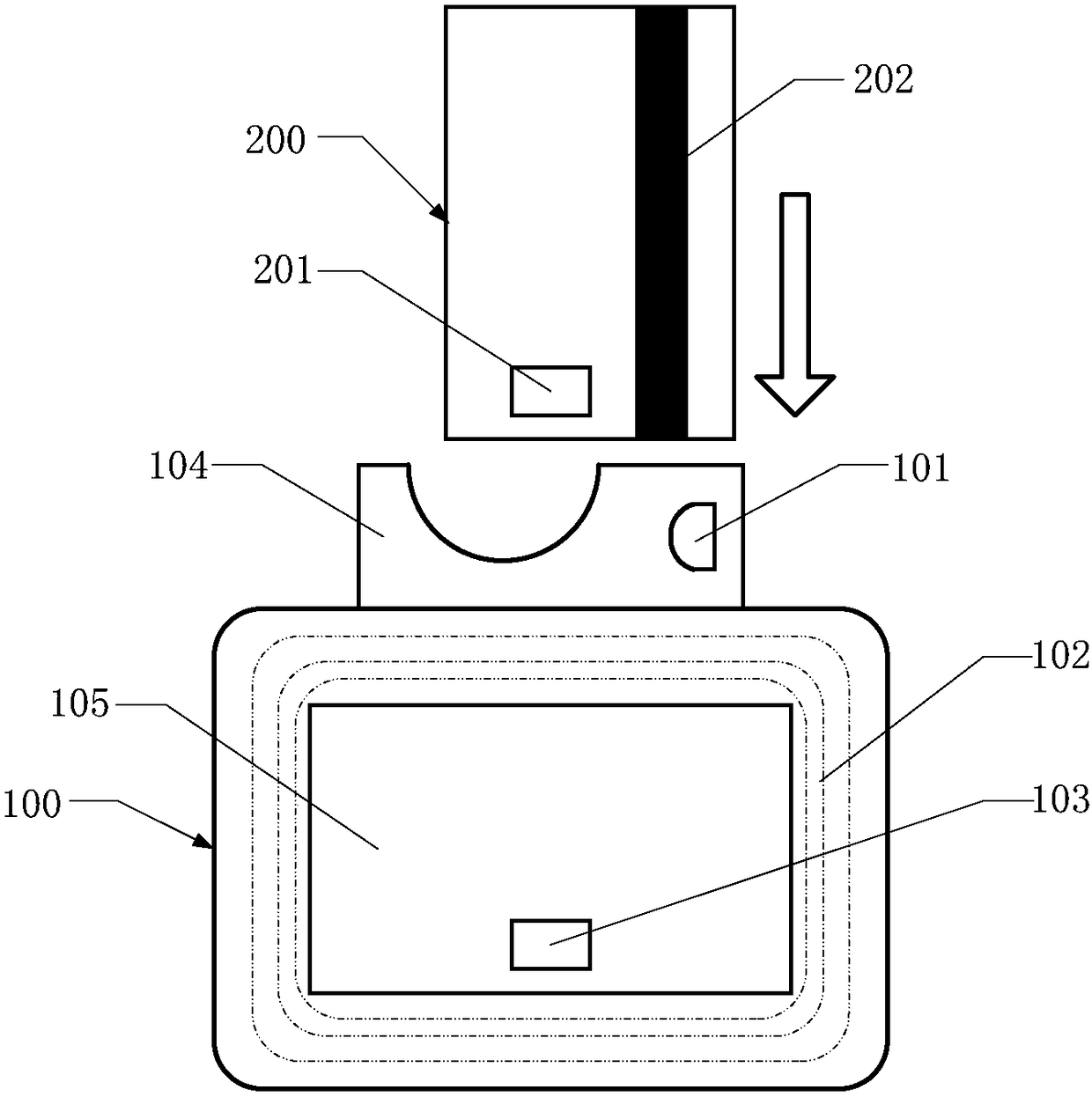
[0037] Such as figure 1 As shown, an exemplary perspective view of a small-volume payment terminal is shown, the payment terminal includes a main body 100, a magnetic card reader 101, a non-contact IC card coil 102 and a contact IC card reader 103, and the magnetic card reader 1 The non-contact IC card coil 2 is arranged around the card slot 105 of the main body 100 , and the contact IC card reading head 103 is set at the bottom of the card slot 105 .

[0038] The payment terminal provided by this embodiment has both magnetic stripe card, contact IC card and non-contact IC card card reading functions, and can read at least one of magnetic stripe card, contact IC card and non-contact IC card. function card.

[0039] Such as figure 1 As shown, when the payment terminal provided by this embodiment realizes the magnetic stripe card or contact IC card reading function, the contact IC card chip 201 of the card 200 faces the card insertion port 104, and the magnetic stripe 202 face...

Embodiment 2

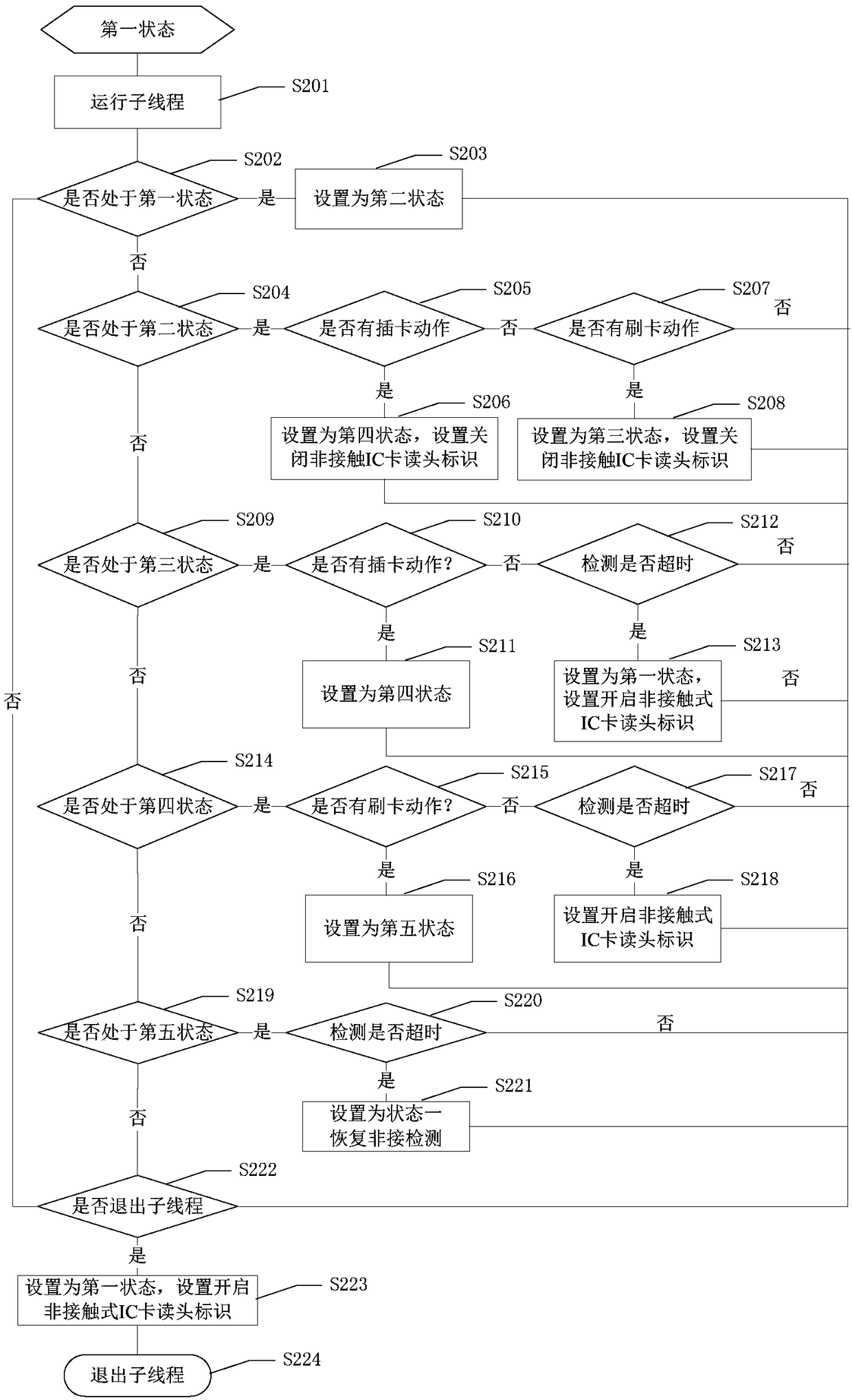
[0061] This embodiment is a further refinement of step S20 in Embodiment 1. It specifically discloses the process of detecting the card swiping state. According to the current card swiping state, the timing of detecting the card reading action can be determined, so that when the card is in the appropriate card swiping state , to trigger the operation of detecting the corresponding card reading action.

[0062] Such as image 3 As shown, in this embodiment, the implementation process of step S20 specifically includes:

[0063] Step S201, running a sub-thread to detect the current card swiping status;

[0064] Step S202, detecting whether the current card swiping state is in the first state, if so, proceed to step S203, otherwise proceed to step S204;

[0065] Step S203, setting the current card swiping status as the second status, and proceeding to step S222;

[0066] Step S204, detecting whether the current card swiping state is in the second state, if so, proceed to step S...

Embodiment 3

[0106] In this embodiment, the payment terminal includes an application layer, an intermediate layer and a system layer, and the methods described in Embodiments 1 and 2 are executed by the intermediate layer. The traditional payment terminal only includes the application layer and the system layer. In this embodiment, by adding an intermediate layer between the application layer and the system layer, it is possible to add an intermediate layer without changing the existing system architecture of the payment terminal. , to implement the above method. The specific implementation is as follows:

[0107] 1. For the system layer, the system interface provided by the system layer is not changed;

[0108] 2. For the intermediate layer, an intermediate interface is set in the intermediate layer. The definition of the intermediate interface is realized by rewriting the definition of the system interface, specifically: rewriting the system interface (mainly the interface about card oper...


PUM


Abstract

The invention provides a card reading method, a payment terminal (POS, Point Of Sale) and terminal equipment, which are suitable for use in the technical field of payment terminals, The card reading method is applied to the payment terminal. The payment terminal has card reading functions of magnetic stripe cards, contact-type IC cards and non-contact-type IC cards. The card reading method includes: opening a magnetic-stripe-card reading head, a contact-type-IC-card reading head and a non-contact-type-IC-card coil; detecting card reading action, wherein the card reading action includes card insertion action, card swiping action and card waving action; shutting down the non-contact-IC-card coil if the card insertion action is detected; carrying out a powering-on operation on a card when thecard reaches the bottom of a card slot of the payment terminal; controlling the contact-type-IC-card reading head to read the card if card powering-on succeeds; controlling the magnetic-stripe-card reading head to read the card when the card swiping action is detected if card powering-on fails; and controlling the non-contact-IC-card coil to read the card if the card waving action is detected. The method effectively eliminates the problem of card reading interference of small-volume payment terminals, and reduces development difficulty of card reading programs.

Description

technical field [0001] The invention belongs to the technical field of payment terminals, and in particular relates to a card reading method, a payment terminal and terminal equipment. Background technique [0002] With the continuous popularization of UnionPay cards and stored-value cards, various payment terminals (POS, Point Of Sale) that can realize the fast payment function of UnionPay cards have emerged in an endless stream, bringing great convenience to people's lives. Existing payment terminals are usually required to have the functions of reading magnetic stripe cards, contact IC cards and non-contact IC cards at the same time. Traditional payment terminals are bulky, and the card-reading areas used to read different types of cards are set separately from each other without interfering with each other. [0003] However, due to the limited space available for setting the card reading area in the existing small-sized payment terminals, the distance between each card ...

Claims


Application Information

Patent Timeline
Patent Type & Authority Applications(China)
IPC IPC(8): G06K7/00
CPCG06K7/0004G06K7/0069G06K7/0091G06K7/084G06K7/10128G06K13/08G07F7/0893G06Q20/352G06Q20/34G06Q20/204
Inventor 周爱平曾检生任家乐王欢
Owner PAX COMP TECH SHENZHEN
Why Eureka
Try Eureka