Automatic demagnetizing device for cylindrical magnetic shielding of atomic clock

A magnetic shielding, atomic clock technology, applied to magnetic objects, electrical components, circuits, etc., can solve the problems of increasing demagnetization current, inability to obtain demagnetization results, and the need for repeated demagnetization, so as to achieve smooth and delicate current changes, safe and reliable demagnetization process. Good demagnetization effect

Active Publication Date: 2018-09-21
NAT TIME SERVICE CENT CHINESE ACAD OF SCI
View PDF7 Cites 1 Cited by
  • Summary
  • Abstract
  • Description
  • Claims
  • Application Information

AI Technical Summary

Problems solved by technology

The power supply of the demagnetization device is 220V, 50Hz mains power. The function of the voltage regulator only changes the intensity of the demagnetization current but cannot change the frequency. Such a single frequency may not be able to obtain the best demagnetization results for magnetic shields with different materials, thicknesses and shapes. , the intensity of the demagnetization current is achieved by sliding the brush of the second voltage regulator on the coil. Generally, the number of coil turns of the voltage regulator is limited, so the intensity of the demagnetization current cannot be adjusted too finely, and the occasional contact between the brush and the coil is poor. It will cause a large change in the demagnetization current, which will have an impact on the magnetic shield
Since the whole demagnetization process is completely completed by manual operation, the demagnetization results are greatly affected by human factors. Different people or even the same person will have different demagnetization results at different times, and sometimes repeated demagnetization is required; and the demagnetization coil is connected to the market through a voltage regulator. Electrically connected, the voltage between the demagnetization coil and the ground is 220V. If a short circuit occurs during the demagnetization process, it will cause an instantaneous increase in the demagnetization current, which will cause irreversible damage to the magnetic shield, and even cause personal injury in severe cases.

Method used


Image

  • Automatic demagnetizing device for cylindrical magnetic shielding of atomic clock

Examples


Embodiment 1

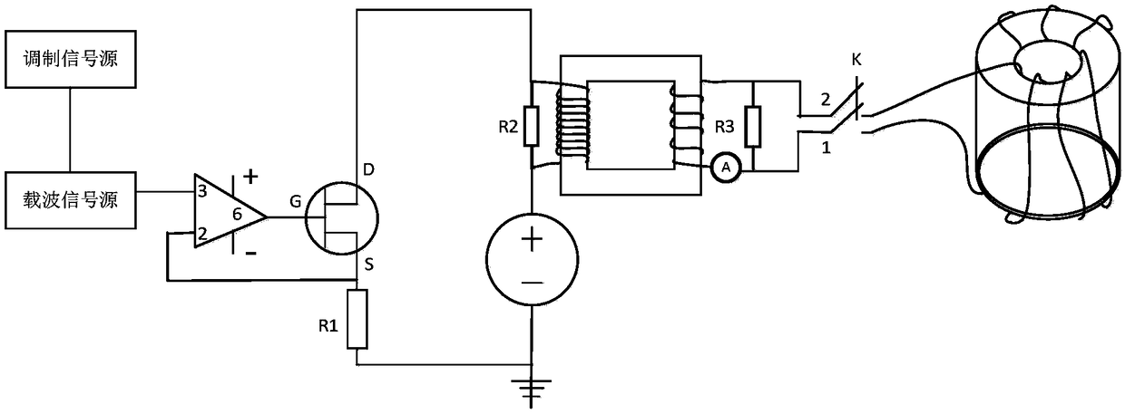
[0016] exist figure 1 Among them, the automatic demagnetization device of the atomic clock cylindrical magnetic shield of the present embodiment is composed of a modulation signal source, a carrier signal source, an operational amplifier, a field effect tube, a resistor R1, a DC power supply, a transformer, a knife switch K, a resistor R2, a resistor R3, and an ammeter A. The demagnetization coil is connected.

[0017] The output end of the modulation signal source is connected to the modulation end of the carrier signal source. The modulation signal source outputs a sinusoidal signal with a frequency of 0.005Hz, which is used to modulate the amplitude of the carrier signal. The carrier signal source outputs a modulated sinusoidal signal with a frequency of 50Hz. The carrier signal source The output terminal of the operational amplifier is connected to the 3-pin of the operational amplifier, the 2-pin of the operational amplifier is connected to the S terminal of the FET and g...

Embodiment 2

[0019] In this embodiment, the output end of the modulation signal source is connected to the modulation end of the carrier signal source, and the modulation signal source outputs a sinusoidal signal with a frequency of 0.002 Hz, which is used to modulate the amplitude of the carrier signal source, and the modulated frequency of the carrier signal source is 20 Hz. Sinusoidal signal. The other components and the connection relationship of the components are the same as in Embodiment 1.

Embodiment 3

[0021] In this embodiment, the output end of the modulation signal source is connected to the modulation end of the carrier signal source. The modulation signal source outputs a sinusoidal signal with a frequency of 0.02 Hz, which is used to modulate the amplitude of the carrier signal source. The modulated frequency of the carrier signal source is 200 Hz. Sinusoidal signal. The other components and the connection relationship of the components are the same as in Embodiment 1.


PUM


Abstract

Provided is an automatic demagnetizing device for cylindrical magnetic shielding of an atomic clock. An output end of a modulation signal source is connected with a modulation end of a carrier wave signal source. An output end of the carrier wave signal source is connected with an input end of a controlled current loop. An output end of the controlled current loop is connected with a demagnetization current loop. The controlled current loop is formed in such a manner that a driving circuit, a direct-current power supply and an input end of a transformer are connected in series. An input end ofthe driving circuit is connected with the output end of the carrier wave signal source. The demagnetization current loop is formed in such a manner than an output end of the transformer, a knife switch and a demagnetization coil are connected in series. The demagnetization coil winds around a magnetic shielding cylinder. The automatic demagnetizing device for cylindrical magnetic shielding of theatomic clock is advantaged by being simple in structure and convenient in operation and is safe and reliable.

Description

technical field [0001] The invention belongs to the technical field of demagnetization equipment, and in particular relates to an atomic clock cylindrical magnetic shield automatic demagnetization device. Background technique [0002] The research of atomic clock needs to add a uniform weak magnetic field (C field) in the atomic interaction area to remove the energy level degeneracy of the atomic ground state and provide the quantization axis of the atomic transition. The size and uniformity of the magnetic field directly affect the performance of atomic clocks. The C field strength of typical atomic clocks (cesium beam clocks, fountain clocks, hydrogen clocks, and spaceborne clocks) is on the order of hundreds of nanotets, and the magnetic field fluctuations in the atomic interaction area are required to be on the order of nanots. Experimentally, if such a weak magnetic field environment is to be generated around the atomic clock device, it is first necessary to shield the...

Claims


Application Information

Patent Timeline
Patent Type & Authority Applications(China)
IPC IPC(8): H01F13/00
CPCH01F13/006
Inventor 王心亮杨帆管勇阮军张首刚
Owner NAT TIME SERVICE CENT CHINESE ACAD OF SCI
Why Eureka
Try Eureka