Rubber assembly fixing device applied to motor

A fixing device and rubber technology, applied in the direction of electromechanical devices, electrical components, electric components, etc., can solve the problems of excessive friction heat generation, increase motor power, etc., to achieve the effect of avoiding friction heat generation, reducing resistance, and simple device structure

Active Publication Date: 2018-09-21
温岭温高教育科技有限公司
View PDF3 Cites 2 Cited by
  • Summary
  • Abstract
  • Description
  • Claims
  • Application Information

AI Technical Summary

Problems solved by technology

[0002] The motor is represented by the letter M in the circuit, and its main function is to generate driving torque. As a power source for electrical appliances or various machines, the generator is represented by the letter G in the circuit. Its main function is to use mechanical energy to convert Electric energy, the main function of the motor is to drive the drive shaft to rotate. The drive shaft will inevitably generate certain vibrations during high-speed rotation. The severe vibration will affect the use of the equipment to a certain extent, so it is often between the motor and the drive shaft. A rubber set is placed on the connection to reduce the vibration that will affect the use of the equipment due to the too rigid contact method. However, the general rubber set is directly sleeved, relying on its own friction to ensure its fixing effect. This method must To a certain extent, the force of the drive shaft rotation is greater. The rubber set may rotate with the drive shaft, which will cause friction with the motor. At the same time, the rubber may also be fixed with the motor, which will cause friction with the drive shaft. The rubber set is in an uncertain state. Excessive heat generation will also increase the power of the motor to drive the drive shaft to rotate

Method used


Image

  • Rubber assembly fixing device applied to motor
  • Rubber assembly fixing device applied to motor
  • Rubber assembly fixing device applied to motor

Examples


Embodiment Construction

[0018] The following will clearly and completely describe the technical solutions in the embodiments of the present invention with reference to the accompanying drawings in the embodiments of the present invention. Obviously, the described embodiments are only some, not all, embodiments of the present invention.

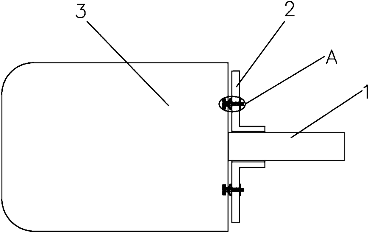
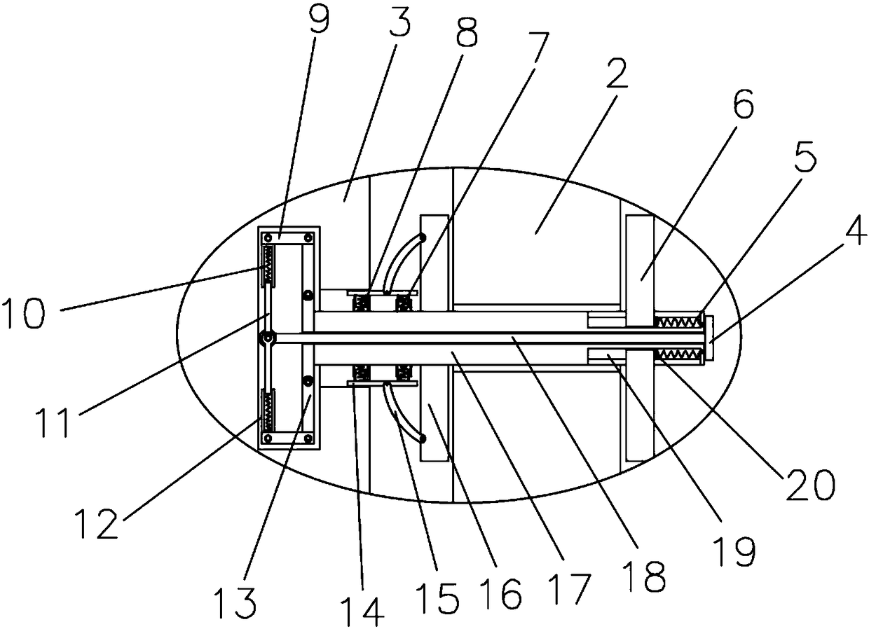
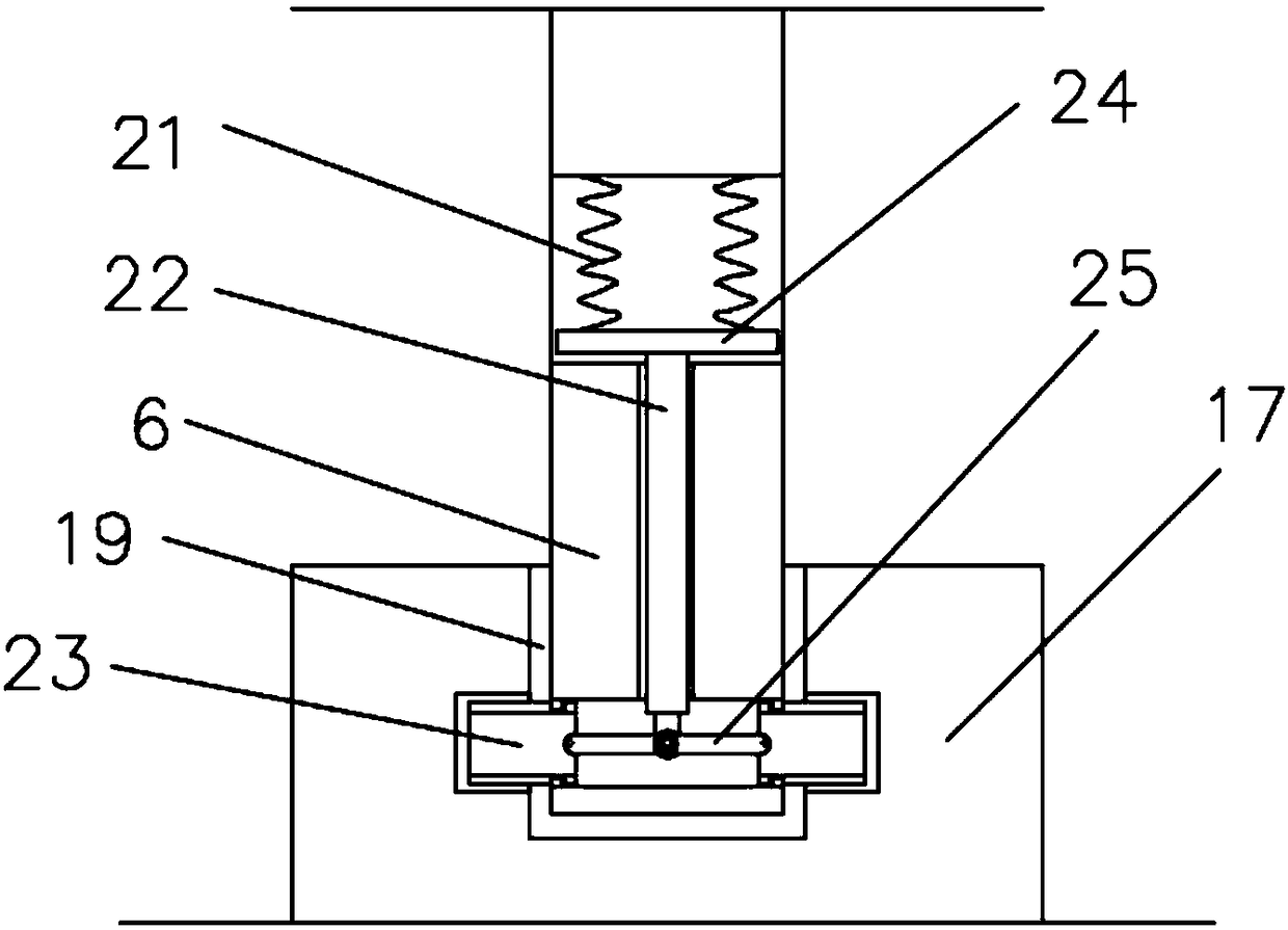
[0019] refer to Figure 1-3 , a rubber sleeve fixing device applied to a motor, comprising a motor 3, a rubber sleeve 2 and a plurality of insertion shafts 17, the rubber sleeve 2 is arranged on the motor 3, a plurality of insertion shafts 17 are inserted on the rubber sleeve 2, and the motor 3 is rotatably connected with the drive shaft 1, the rubber sleeve 2 is sleeved on the drive shaft 1, the motor 3 is provided with a card slot, one end of the insertion shaft 17 is inserted in the card slot, and the insertion shaft 17 is fixedly connected with a fixed sleeve 16 The two sides of the inserting shaft 17 are symmetrically provided with movable plates 14, the movable...


PUM


Abstract

The invention discloses a rubber assembly fixing device applied to a motor. The rubber assembly fixing device comprises a motor, a rubber assembly and a plurality of insertion shafts, wherein the rubber assembly is arranged on the motor; the plurality of insertion shafts are inserted into the rubber assembly; a drive shaft is rotationally connected onto the motor; the rubber assembly is connectedonto the drive shaft in a sleeving manner; clamping grooves are formed in the motor; one ends of the insertion shafts are inserted into the clamping grooves; fixing sleeves are fixedly connected ontothe insertion shafts; movable plates are symmetrically arranged on two sides of the insertion shafts; the movable plates are rotationally connected with an arc-shaped shaft; one end of the arc-shapedshaft is rotationally connected with the fixing sleeves. The rubber assembly fixing device disclosed by the invention is simple in structure; due to mutual match of the insertion shafts, the fixing sleeves and the clamping shaft, the position of the rubber assembly can be fixed, the phenomenon that rotation of the drive shaft is obstructed due to optional movement is avoided, the resistance is efficiently reduced, and unnecessary friction heat is avoided, so that the rubber assembly fixing device applied to the motor is provided for a user.

Description

technical field [0001] The invention relates to the technical field of rubber sleeves, in particular to a rubber sleeve fixing device applied to a motor. Background technique [0002] The motor is represented by the letter M in the circuit, and its main function is to generate driving torque. As a power source for electrical appliances or various machines, the generator is represented by the letter G in the circuit. Its main function is to use mechanical energy to convert Electric energy, the main function of the motor is to drive the drive shaft to rotate. The drive shaft will inevitably generate certain vibrations during high-speed rotation. The severe vibration will affect the use of the equipment to a certain extent, so it is often between the motor and the drive shaft. A rubber set is placed on the connection to reduce the vibration that will affect the use of the equipment due to the too rigid contact method. However, the general rubber set is directly sleeved, relying...

Claims


Application Information

Patent Timeline
IPC IPC(8): H02K5/24
CPCH02K5/24
Inventor 叶星辰
Owner 温岭温高教育科技有限公司
Why Eureka
Try Eureka