
Clamp used for blade inspection
A fixture and blade technology, applied in the field of blade detection fixtures, can solve the problems of low detection efficiency, high detection cost, complicated operation, etc., and achieve the effects of simple detection steps, simplified detection steps, and cost reduction.
- Summary
- Abstract
- Description
- Claims
- Application Information
AI Technical Summary
Problems solved by technology
Method used
Image

Examples
Embodiment Construction
[0023] The embodiments of the present invention will be described in detail below with reference to the accompanying drawings, but the present invention can be implemented in many different ways defined and covered by the claims.
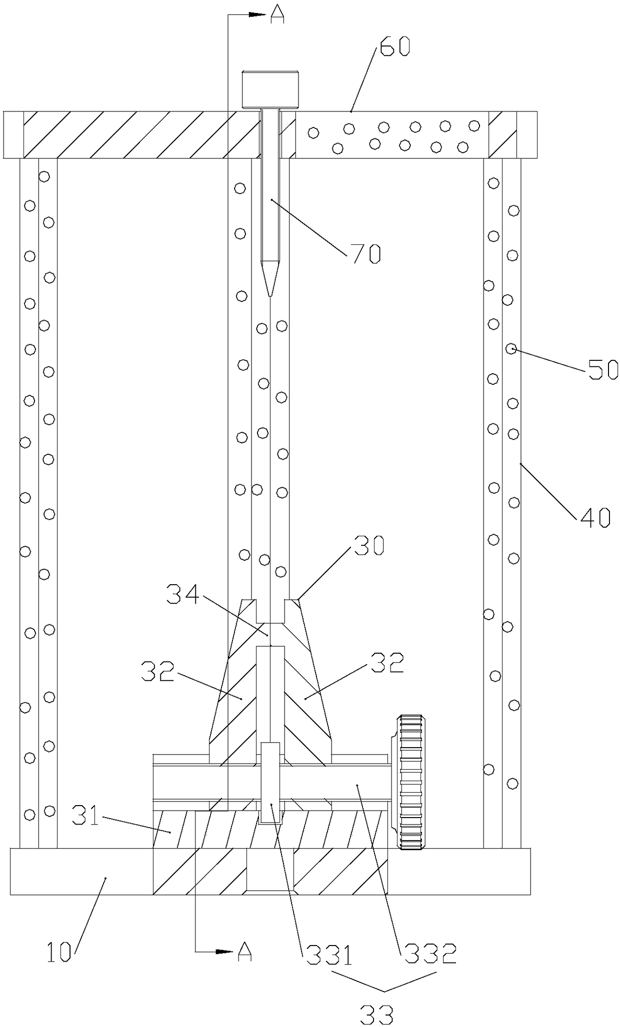
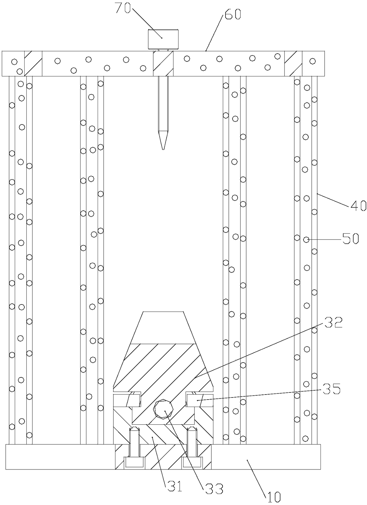
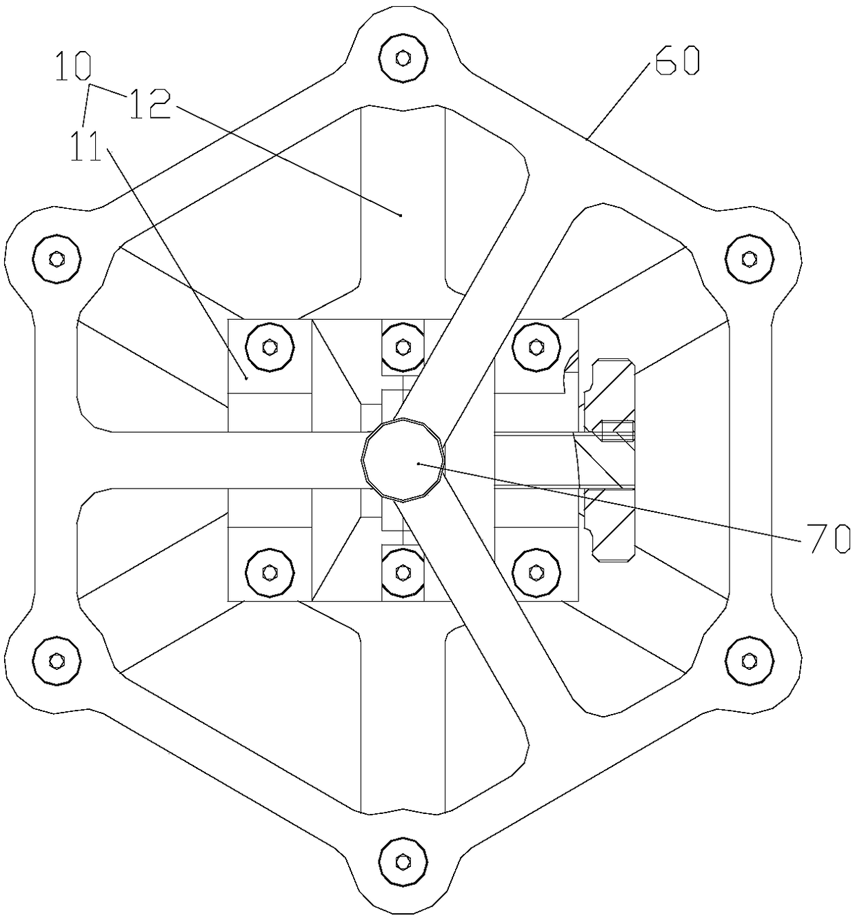
[0024] refer to figure 1 , a preferred embodiment of the present invention provides a fixture for blade detection, including: a mounting base 10 fixed to a rotating table of a three-dimensional scanner (not shown in the figure), and a mounting base 10 is fixed on the mounting base 10 for clamping the blade to be detected. (not shown in the figure) clamp body 30, the four sides of clamp body 30 are provided with a plurality of vertical installation pillars 40, the bottom end of each installation pillar 40 is fixed with the installation base plate 10, and a plurality of installation pillars 40 surrounds and The formed enclosing circle sets the blade circle to be tested clamped by the clamp body 30 therein. A plurality of lighting points 50 are pasted...
PUM
 Abstract
Description
Claims
Application Information