
A Parameter Estimation Method Based on Undersampling Phase-encoded Signal

A phase encoding signal and parameter estimation technology, which is applied in the field of parameter estimation of phase encoding signals, can solve the problem of high sampling rate and achieve the effect of reducing pressure

Active Publication Date: 2021-05-28
HARBIN INST OF TECH
View PDF6 Cites 0 Cited by
  • Summary
  • Abstract
  • Description
  • Claims
  • Application Information

AI Technical Summary

Problems solved by technology

[0018] The purpose of the present invention is to propose a parameter estimation method based on under-sampled phase-encoded signals in order to solve the problem that the existing sampling rate is too high

Method used


Image

  • A Parameter Estimation Method Based on Undersampling Phase-encoded Signal
  • A Parameter Estimation Method Based on Undersampling Phase-encoded Signal
  • A Parameter Estimation Method Based on Undersampling Phase-encoded Signal

Examples


specific Embodiment approach 1

[0035] Specific embodiment one: a kind of parameter estimation method based on the undersampled phase encoding signal comprises the following steps:

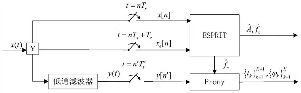
[0036] Aiming at the parameter estimation problem of MPSK signal, the present invention proposes an under-sampling method based on multi-channel parallel structure. There are three channels in this structure; channel 1 and channel 2 perform dual-channel delay sampling on the signal, and use the rotating subspace invariant (ESPRIT) algorithm to estimate the signal carrier frequency. Channel three first performs low-pass filtering on the signal, and then samples at a low speed to obtain a continuous Fourier series coefficient at the low frequency of the signal; combined with the carrier frequency estimated by channel one and channel two, the Prony algorithm is used to estimate the signal The amplitude, discontinuity point, and phase information of the signal. The specific structure diagram is as figure 1 shown.

[0037] Step 1:...

specific Embodiment approach 2

[0042] Specific embodiment two: the difference between this embodiment and specific embodiment one is: the expression of the phase encoding signal x(t) in the step one is:

[0043]

[0044] Where t is time, A is signal amplitude, f c is the signal carrier frequency, τ is the signal duration, and K is the number of segments separated by the signal due to phase jumps; is the phase of each segment, is the initial phase, c(k) is the value of the input symbol, and the possible values ​​are M is the base number of phase modulation, q is an intermediate variable, ξ k (t) is an intermediate variable, ξ k (t)=u(t-t k )-u(t-t k+1 ), 0≤t 1 K+1 k is the position of the discontinuity point caused by the phase mutation.

[0045] Other steps and parameters are the same as those in Embodiment 1.

specific Embodiment approach 3

[0046] Specific embodiment three: the difference between this embodiment and specific embodiment one or two is: x[n] and x in the second step e The expression of [n] is:

[0047]

[0048]

[0049] Where n is a discrete count value.

[0050] Other steps and parameters are the same as those in Embodiment 1 or Embodiment 2.


PUM


Abstract

A method for estimating parameters of phase coded signals based on subsampling, and the invention relates to a method for estimating parameters of phase coded signals. The present invention aims to solve the problem that the existing sampling rate is too high. The multi-channel parallel sampling system proposed by the present invention can realize under-sampling of MPSK signals under the premise of known signal modulation type, and the lowest equivalent sampling rate is only for accurate estimation of signal parameters. When the signal frequency is high, the sampling method of the present invention can complete sampling and parameter estimation at a rate much lower than the Nyquist sampling frequency, thereby greatly reducing the pressure on sampling equipment. For a band-limited signal with a bandwidth of B, the sampling rate of the present invention is a multiple of the Nyquist sampling rate. For non-band-limited signals, Nyquist sampling cannot realize sampling without information loss in theory, and the sampling rate of the present invention is used in the field of radar signal processing.

Description

technical field [0001] The invention relates to the field of radar signal processing, in particular to a parameter estimation method based on under-sampled phase coded signals. Background technique [0002] Phase-encoded signal is one of the pulse compression modulation methods, which has the advantages of high resolution and strong anti-interference ability, so it is widely used in pulse compression radar, and can obtain a large time-width-bandwidth product. At the same time, the signal is also widely used in digital communication systems. Commonly used phase encoding signals include binary phase shift keying (Binary Phase Shift Keying, BPSK), quadrature phase shift keying (Quadrature Phase Shift Keying, QPSK) and other forms. In the field of electronic reconnaissance, in order to obtain effective information from enemy radar, it is necessary to identify the radar modulation mode and estimate the modulation parameters of the radar signal. In a non-cooperative electronic e...

Claims


Application Information

Patent Timeline
Patent Type & Authority Patents(China)
IPC IPC(8): G01S7/292
CPCG01S7/292
Inventor 付宁黄国兴曹杰邓立宝乔立岩
Owner HARBIN INST OF TECH
Learn More