
A pneumatic glue filling device

A pneumatic and glue-filling technology, which is applied to the device, transportation and packaging, coating and other directions of coating liquid on the surface, which can solve the problem of air bubbles between A glue and B glue, inaccurate proportion of A glue and B glue, etc. Affect the quality and reliability of mixed rubber products, and achieve the effect of accurate proportion, quality assurance and reliability of use

Active Publication Date: 2019-09-20
GREE ELECTRIC APPLIANCES INC
View PDF7 Cites 0 Cited by
  • Summary
  • Abstract
  • Description
  • Claims
  • Application Information

AI Technical Summary

Problems solved by technology

[0003] Since the air inlet pipe and the rubber outlet pipe of the existing pneumatic glue filling machine are arranged on the top of the glue dispensing barrel, the high-pressure compressed air in the inlet pipe enters the glue dispensing barrel and easily enters the glue in the glue distributing barrel and cannot be discharged. , leading to the presence of air bubbles in the extruded A glue and B glue
At the same time, glue A and glue B at the glue nozzle cannot be fully mixed, resulting in an inaccurate glue volume ratio between glue A and glue B, which affects the quality of the mixed glue and the reliability of the product.

Method used


Image

  • A pneumatic glue filling device

Examples


Embodiment Construction

[0025] The present invention is described below based on the embodiments, and those skilled in the art should understand that the drawings provided here are for the purpose of illustration, and the drawings are not necessarily drawn to scale.

[0026] Unless the context clearly requires, throughout the specification and claims, "comprises", "comprises" and similar words should be interpreted in an inclusive sense rather than an exclusive or exhaustive meaning; that is, "including but not limited to" meaning.

[0027] Explanation: The up and down directions involved in this application are as follows figure 1 The orientation shown in is applicable.

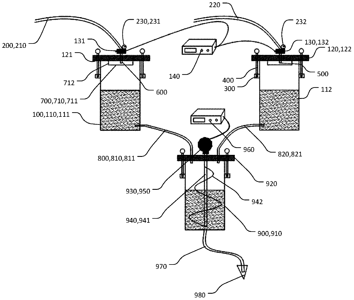
[0028] like figure 1 As shown, the application provides a pneumatic glue filling device, including an air supply part (not shown in the figure) and at least one container 100 for holding the glue, wherein the air supply part passes into the container 100 without The colloid in the container 100 reacts with gas, and the gas suppl...


PUM


Abstract

The invention provides a pneumatic glue filling device, comprising an air supply part and at least one container for containing glue, the container includes an air inlet, and the air supply part enters the container through the air inlet Introduce pressure gas, the air inlet does not face the colloid in the container and / or a deceleration structure is provided between the air inlet and the colloid in the container, and the deceleration structure is used to reduce the pressure caused by the colloid. The flow rate of the gas flow from the air inlet to the colloid. The pneumatic glue filling device in this application can prevent the occurrence of air bubbles in the glue by feeding the air inlet not towards the glue in the container or setting a deceleration structure between the air inlet and the glue, thereby ensuring The proportion of the colloid is more accurate during the mixing process, which ensures the quality and reliability of the colloid.

Description

technical field [0001] The invention relates to the field of glue filling, in particular to a pneumatic glue filling device. Background technique [0002] The existing pneumatic double-liquid manual glue filling machine relies on the air pressure to squeeze out the A glue from the A component glue barrel and the B glue from the B component glue barrel when filling the glue, and then enters the belt. There is a glue nozzle with the function of adjusting the ratio of A and B glue to mix and pour glue. [0003] Since the air inlet pipe and the rubber outlet pipe of the existing pneumatic glue filling machine are arranged on the top of the glue dispensing barrel, the high-pressure compressed air in the inlet pipe enters the glue dispensing barrel and easily enters the glue in the glue distributing barrel and cannot be discharged. , resulting in air bubbles in the extruded glue A and glue B. At the same time, glue A and glue B at the glue nozzle cannot be fully mixed, resulting...

Claims


Application Information

Patent Timeline
Patent Type & Authority Patents(China)
IPC IPC(8): B05C11/10B05C11/11B05C5/02B01F11/00B01F15/00B01F15/02
CPCB05C5/02B05C11/1013B05C11/1036B05C11/11B01F31/445B01F31/443B01F31/449B01F35/2113B01F35/2211B01F35/71745B01F2101/36
Inventor 刘洪明刘秤明覃武车伏龙覃冬梅赵志刚颜冬博黄毅翔王刚王春阳
Owner GREE ELECTRIC APPLIANCES INC
Learn More