Piezoelectric liquid injector

Inactive Publication Date: 2007-03-29
AXIAL VECTOR ENGINE CORP
View PDF0 Cites 12 Cited by
  • Summary
  • Abstract
  • Description
  • Claims
  • Application Information

AI Technical Summary

Benefits of technology

[0006] It is a further object of the present invention to provide such a high frequency fuel injector, which is scalable, and small and lightweight.
[0007] It is yet another object of the present invention to provide such a high frequency fuel injector, which is piezoelectric actuated, and has the ability to inject very small amounts of fuel as well as greater amounts of fuel required at full power.
[0008] The fuel injector of the present invention is simple to build, easy to assemble, and simple to calibrate; yet is able to handle high compression rates for late injection, and to disperse the fuel into particles 12 Microns or smaller.
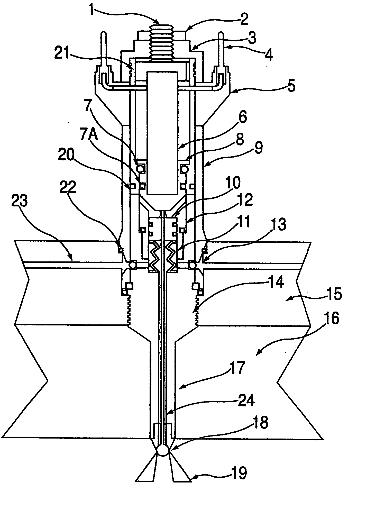
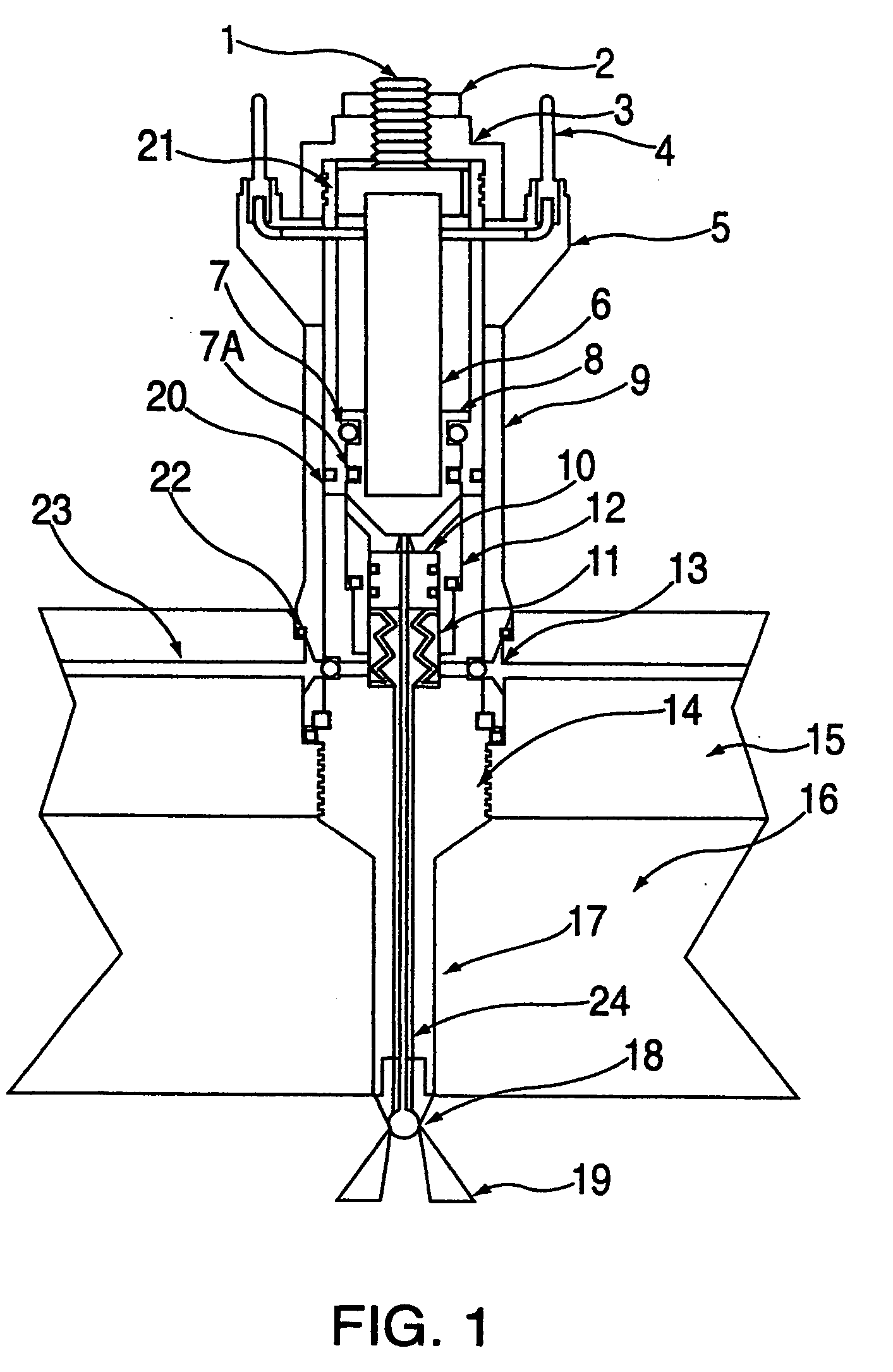
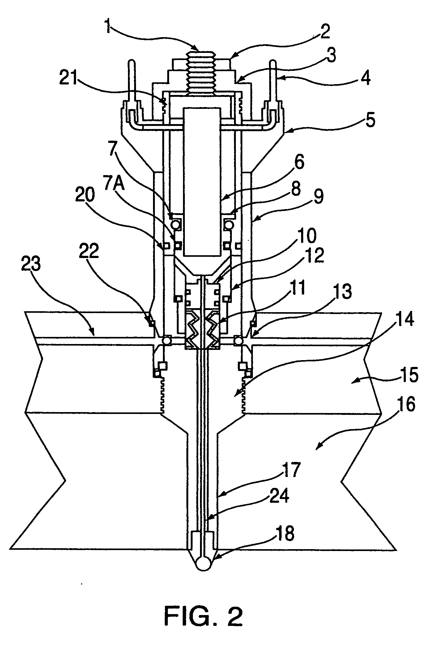
[0009] These objects, as well as other objects which will become apparent from the discussion that follows, are achieved, in accordance with the present invention, which comprises a piezoelectric liquid injector, which comprises a needle valve disposed within a housing so as to define at least two hydraulic chambers, each with a fluid inlet. The needle valve is contained in the housing by a proximal retaining cap, attached to an outer sleeve, attached to the main fuel injector body, comprising means of attachment to e.g., a fuel rail, with the distal end extending into a combustion chamber. The injector further comprises a piezoelectric actuator the proximal end of which is contained by a piezo end cap, secured within the retaining cap. The piezoelectric actuator bears a hydraulic acceleration piston on its distal end. Upon the application of a controlled voltage, the actuator expands, moving the piston through the upper hydraulic chamber toward the proximal end of the needl

Problems solved by technology

Late injection of fuel does not induce a lot of mixing, resulting in uneven combustion.
To comp

Method used


Image

  • Piezoelectric liquid injector
  • Piezoelectric liquid injector
  • Piezoelectric liquid injector

Examples


Example

[0018] It is worthy to note that any reference herein to “one embodiment” or “an embodiment” means that a particular feature, structure, or characteristic described in connection with the embodiment is included in at least one embodiment of the invention. The appearances of the phrase “in one embodiment” in various places in the specification are not necessarily all referring to the same embodiment.

[0019] An exemplary embodiment of the present invention will now be described with reference to FIGS. 1 to 5 of the drawings. Identical elements in the various figures are designated with the same reference numerals.

[0020] A Piezo stack actuator works much like a spring. It is built of many layers like the coils on a spring. Each layer expands a given rate if voltage is applied to the crystal. Each layer on a Piezo actuator expands anywhere from 50 nanometers to 200 nanometers, depending on the material. In order to create a Piezo stack actuator with a travel of 40 micrometers; if the b...


PUM


Abstract

A fuel or liquid injector includes a needle valve and a piezoelectric actuator that bears a hydraulic acceleration piston on its distal end. The actuator expands moving the piston toward the needle valve. The needle valve has a ball end, restrained against the valve seat by a spring, sealing the valve until the spring force is overcome by mechanical and hydraulic forces on the piston. When closed, the piston rests against the needle valve. Expansion of the piezoelectric actuator mechanically actuates the piston, and then increases the hydraulic pressure, which closes the fuel check valve, and accelerates the forward movement of the piston attached to the needle valve. When the restraining force on the needle valve is overcome, the ball end of the needle valve is unseated, and compressed fluid in the lower hydraulic chamber is released in a high velocity spray.

Description

CROSS REFERENCE TO RELATED APPLICATION [0001] This application claims the benefit of the earlier filing of U.S. Provisional Application No. 60 / 709,082 filed on Aug. 17, 2005 incorporated herein in its entirety.FIELD OF THE INVENTION [0002] The present invention relates generally to liquid injectors for use in supplying pressurized liquids. More particularly, the present invention relates to a liquid injector for use in supplying pressurized liquid, which injector is piezoelectrically actuated. BACKGROUND [0003] Standard fuel injectors, including piezoelectric actuated fuel injectors, are designed to inject a given amount of fuel at very high pressures for good atomization of the fuel. Existing fuel injectors inject fuel at various points in the Otto cycle. Various approaches have been used to achieve a homogenous air and fuel mixture. Fuel injected during the intake stroke is typically injected into the intake air stream, not directly into the combustion chamber. The fuel is injecte...

Claims


Application Information

Patent Timeline
IPC IPC(8): B05B3/04
CPCF02M51/0603F02M2200/703F02M61/167F02M61/08
Inventor BOGNER, ERWIN
Owner AXIAL VECTOR ENGINE CORP
Why Eureka
Try Eureka