Position detection system and position detection method

Active Publication Date: 2019-03-14
MURATA MFG CO LTD
View PDF0 Cites 0 Cited by
  • Summary
  • Abstract
  • Description
  • Claims
  • Application Information

AI Technical Summary

Benefits of technology

This patent is about a system and method that can detect your position accurately without the need for multiple sensors. It works by measuring the phase difference between two signals, and calculating the position based on the difference between those phases. This approach is simpler and more accurate than previous methods.

Problems solved by technology

However, there are problems in that decreasing the pulse width increases occupied bandwidth and it is necessary to perform complicated processing in order to synchronize the respective fixed stations with high accuracy.
However, since it is necessary to control the directivity of antennas of the reference station and the relay station in order to measure the direction, there is a problem in that the processing is made complicated.
In addition, since the range in which the position of the mobile terminal is capable of being identified is limited to a rectangular shape, there is a problem in that the location and the condition in which the position identification apparatus is used are limited.

Method used


Image

  • Position detection system and position detection method
  • Position detection system and position detection method
  • Position detection system and position detection method

Examples


first embodiment

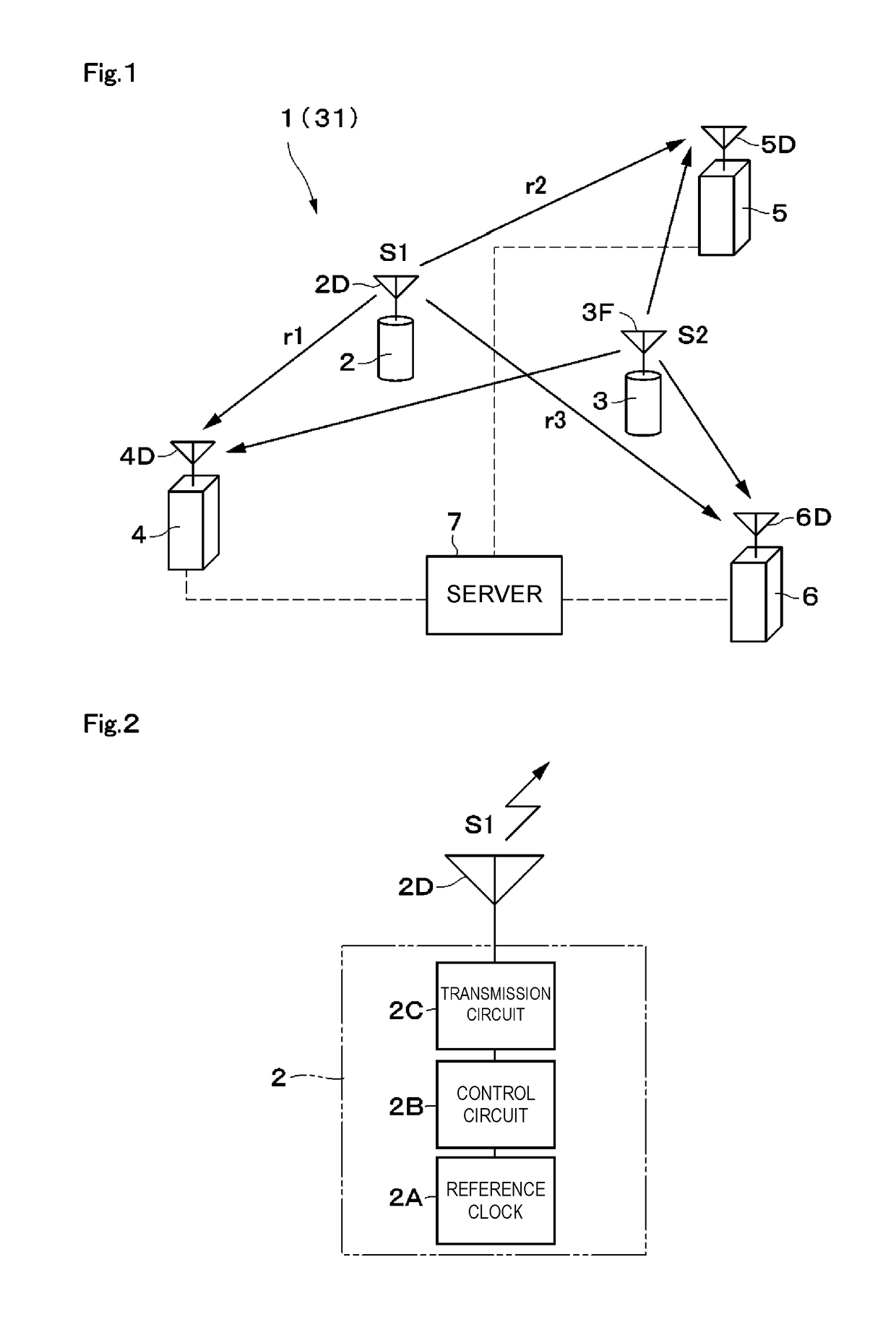
[0047]A position detection system 1 is described with reference to FIG. 1 to FIG. 10. The position detection system 1 includes a mobile station 2, a reference station 3, a first fixed station 4, a second fixed station 5, a third fixed station 6, a server 7, and so on. In this case, for example, it is assumed that the mobile station 2 is apart from the first fixed station 4 by a distance r1, the mobile station 2 is apart from the second fixed station 5 by a distance r2, and the mobile station 2 is apart from the third fixed station 6 by a distance r3.

[0048]The mobile station 2 is, for example, a movable radio terminal that can be a detection target. As illustrated in FIG. 2, the mobile station 2 includes a mobile station reference clock circuit 2A, a control circuit 2B, a radio signal transmission circuit 2C, a transmission antenna 2D, and so on. This mobile station 2 transmits a first radio signal S1 to each of the fixed stations 4 to 6 and transmits a trigger radio signal St to th...

third embodiment

[0119]Next, a position detection method performed by the position detection system 31 will now be described with reference to FIG. 14 to FIG. 16.

[0120]Referring to FIG. 16, Step 21 indicates a specific example of the first radio signal transmission element. In Step 21, the mobile station 2 transmits the first radio signal S1 to each of the fixed stations 4 to 6 and transmits the trigger radio signal St used by the reference station 3 to transmit the second radio signal S2 (refer to FIG. 14).

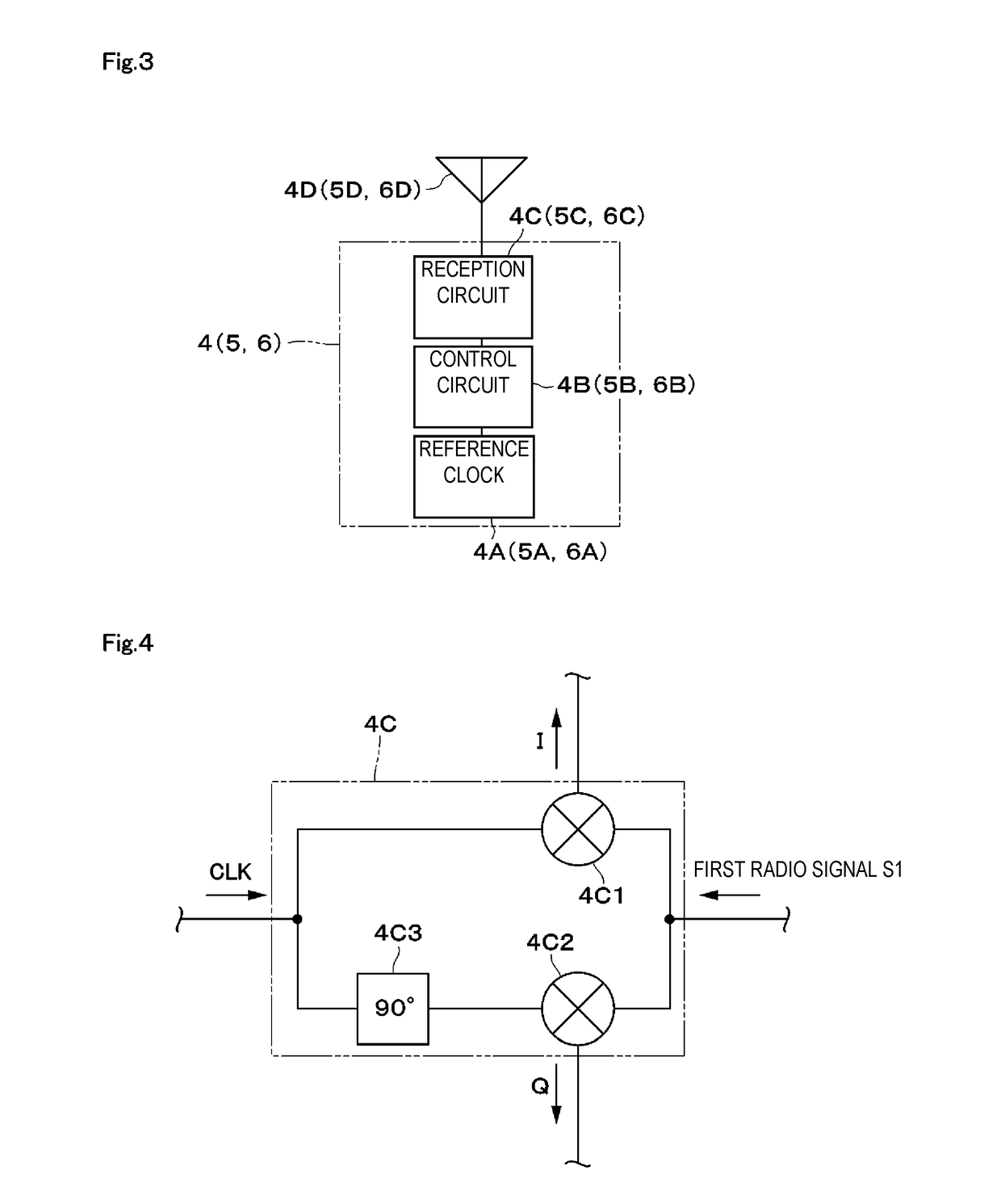
[0121]Step 22 indicates a specific example of the first phase difference calculation element. In Step 22, the respective fixed stations 4 to 6 calculate the phase differences Δϕmf1 to Δϕmf3 between the carrier phase Pm of the received first radio signal S1 and the phases Pf1 to Pf3 of the reference clocks Cf1 to Cf3 (refer to Formula 6 to Formula 12).

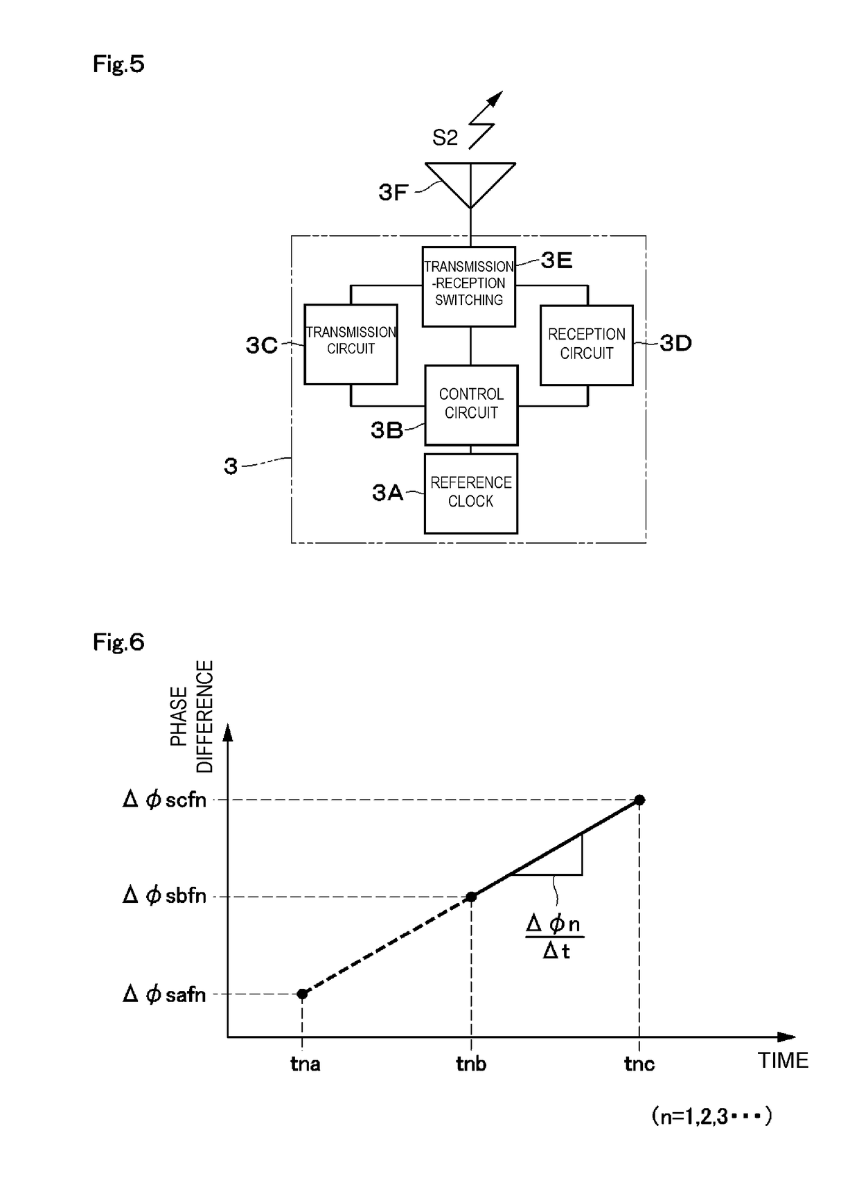
[0122]Step 23 indicates a specific example of the second radio signal transmission element. In Step 23, the reference station 3, which has received...

second embodiment

[0154]The first fixed station 22 is configured so as to also function as the reference station and transmit the second radio signal S2 to each of the fixed stations 5 and 6 in the However, the present disclosure is not limited to this configuration and the second fixed station or the third fixed station may be configured so as to also function as the reference station and transmit the second radio signal. In addition, among the fixed stations, two or more fixed stations may be configured so as to also function as the reference station and transmit the second radio signal.

[0155]The mobile station reference clock circuit 2A is configured so as to have the function to generate the reference clocks Cm and Cm′ of the two angular frequencies ωm and ωm′, and the mobile station is configured so as to transmit the first radio signals S1 and S1′ of the two kinds in the third embodiment. However, the present disclosure is not limited to this configuration. The mobile station reference clock c...


PUM


Abstract

A position detection system includes a mobile station, a reference station, fixed stations to, and a server. The mobile station transmits a first radio signal S1 and the reference station transmits a second radio signal S2 multiple times. Each of the fixed stations extracts a first phase difference based on the first radio signal S1 and extracts second phase differences based on the second radio signals S2. The server calculates time variations of the second phase differences based on the multiple second phase differences to calculate a third phase difference. The server cancels phase offset by the respective fixed stations using phase difference information between the mobile station and the respective fixed stations and phase difference information between the reference station and the respective fixed stations and acquires distance information between the respective fixed stations and the mobile station to calculate the position of the mobile station.

Description

[0001]This is a continuation of International Application No. PCT / JP2017 / 018731 filed on May 18, 2017 which claims priority from Japanese Patent Application No. 2016-104267 filed on May 25, 2016. The contents of these applications are incorporated herein by reference in their entireties.BACKGROUND OF THE DISCLOSUREField of the Disclosure[0002]The present disclosure relates to a position detection system and a position detection method that detect the position of a mobile station.Description of the Related Art[0003]Position detection systems are generally known, which includes multiple fixed stations (base stations) and a mobile station, the multiple fixed stations each of which receives pulse signals transmitted from the mobile station, and calculates the positional relationship between the fixed stations and the mobile station from the difference between the reception times when the fixed stations have received the pulse signals.[0004]In addition, position identification apparatuse...

Claims


Application Information

Patent Timeline
IPC IPC(8): G01S5/06G01S5/02
CPCG01S5/06G01S5/0221G01S5/021H04W56/0035H04W56/0015G01S5/02216H04L7/00
Inventor TAKIZAWA, KOICHI
Owner MURATA MFG CO LTD
Why Eureka
Try Eureka