
Hand lifting-copied cereal impurity removing device

A hand-raised, grain-based technology, applied in the direction of solid separation, separating solids from solids with airflow, chemical instruments and methods, etc., can solve the problems of low screening efficiency, poor impurity removal effect, poor operation quality, etc., and achieve Improve the effect of impurity removal, novel design, and strong practicability

Inactive Publication Date: 2018-09-28
台州来智科技有限公司
View PDF3 Cites 10 Cited by
  • Summary
  • Abstract
  • Description
  • Claims
  • Application Information

AI Technical Summary

Problems solved by technology

[0002] At present, in the field of agriculture, manual and mechanized removal are often used to remove straw flocs and dry and inferior grains in the grain. In manual removal, workers remove the sundries in the grain under the action of natural wind, which requires repeated operations. Carried out, it took a lot of manpower to make the impurity removal not thorough enough. In the mechanized removal of impurities, only one-time treatment led to the incomplete removal of impurities
[0003] At present, most of the separation machines for light and heavy impurities in grains are ordinary drum screens. This type of equipment generally has the disadvantages of poor operation quality and low screening efficiency. This equipment can only complete the primary cleaning of impurities in grains, and can only be cleaned according to the grain The particle diameter is used for sieving, the impurity removal efficiency is low, and the impurity removal effect is poor

Method used


Image

  • Hand lifting-copied cereal impurity removing device
  • Hand lifting-copied cereal impurity removing device
  • Hand lifting-copied cereal impurity removing device

Examples


Embodiment Construction

[0018] The following will clearly and completely describe the technical solutions in the embodiments of the present invention with reference to the accompanying drawings in the embodiments of the present invention. Obviously, the described embodiments are only some, not all, embodiments of the present invention. Based on the embodiments of the present invention, all other embodiments obtained by persons of ordinary skill in the art without making creative efforts belong to the protection scope of the present invention.

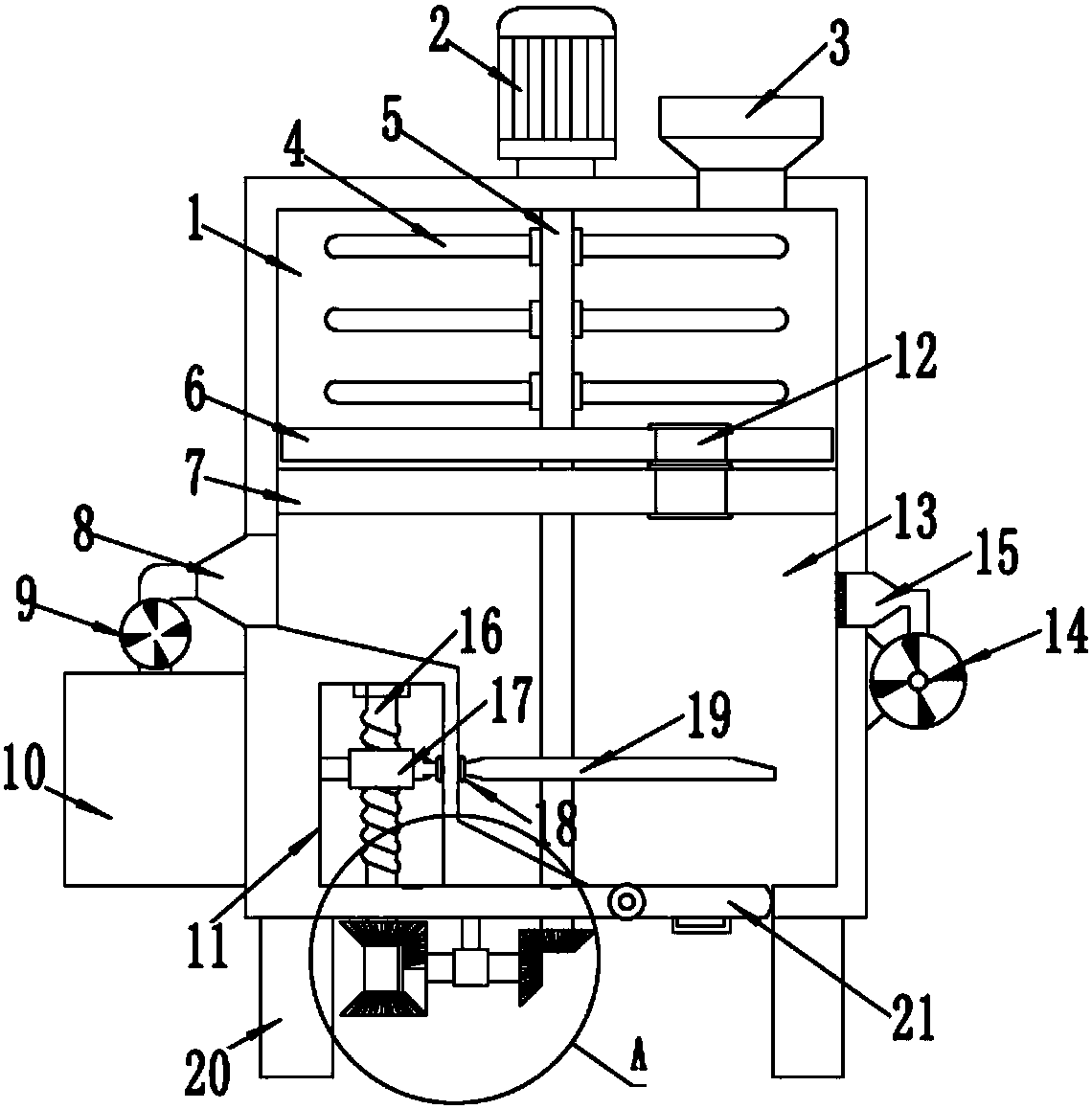
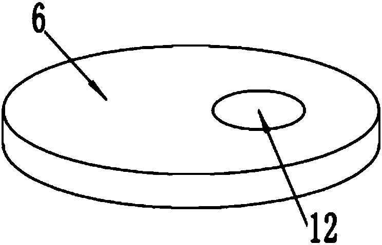
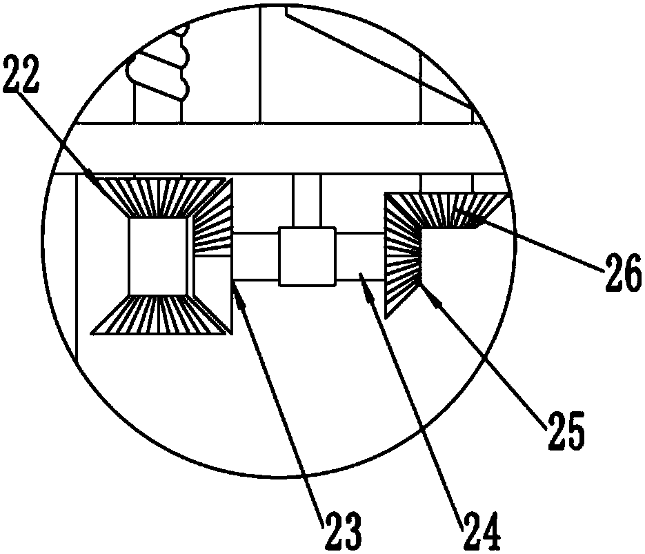
[0019] see Figure 1~3 , in the embodiment of the present invention, a hand-raised grain impurity removal device includes a stirring chamber 1, a motor 2, a bottom plate 7, a collection chamber 10, a transmission chamber 11, and an impurity removal chamber 13; the stirring chamber 1 is arranged in The upper end of the impurity removal chamber 13 is separated by the bottom plate 7, and the lower end of the impurity removal chamber 13 is symmetrically equipped w...


PUM


Abstract

The invention discloses a hand lifting-copied cereal impurity removing device. The hand lifting-copied cereal impurity removing device comprises a stirring cavity, a motor, a base plate, a collectingcavity, a transmission cavity and an impurity removing cavity; the stirring cavity is arranged at the upper end of the impurity removing cavity, and is separated through a base plate; a feed hopper isarranged at the upper end of the stirring cavity; the motor is arranged on the left side of the feed hopper; an output end of the motor is fixedly connected with a rotating shaft; a baffle plate is fixedly mounted on the rotating shaft at the lower end of the inner side of the stirring cavity; a transmission cavity is formed in the left end of the inner side of the impurity removing cavity; a thread rod on the inner side of the transmission cavity is in threaded connection with a thread sleeve; and the right side of the thread sleeve is hinged with a poking plate. The hand lifting-copied cereal impurity removing device is novel in design; when a blanking hole is staggered from or overlapped with a blanking hole on the base plate, cereals fall down through the blanking holes; and when thetwo blanking holes are staggered from each other, the cereals are stopped from falling to achieve an intermittent unloading effect and to effectively prevent influence on the dust flying effect due tosynchronous falling of excessive cereals.

Description

technical field [0001] The invention relates to an impurity removal device, in particular to a hand-raised grain impurity removal device. Background technique [0002] At present, in the field of agriculture, manual and mechanized removal are mostly used to remove straw flocs and dry and inferior grains in the grain. In manual removal, workers remove the sundries in the grain under the action of natural wind, which requires repeated operations. It takes a lot of manpower to remove the impurities thoroughly, and in the mechanized removal of impurities, only one-time treatment leads to the insufficient removal of impurities. [0003] At present, most of the separation machines for light and heavy impurities in grains are ordinary drum screens. This type of equipment generally has the disadvantages of poor operation quality and low screening efficiency. This equipment can only complete the primary cleaning of impurities in grains, and can only be cleaned according to the grain ...

Claims


Application Information

Patent Timeline
IPC IPC(8): B07B4/02B07B11/06B07B11/00
Inventor 郑贝贝
Owner 台州来智科技有限公司
Learn More