
Three-phase power autotransformer

A technology of power transformers and autotransformers, which is applied in the field of transformers, can solve problems such as inconvenience, and achieve the effects of maintaining the working environment, prolonging the service life, and ensuring normal operation

Inactive Publication Date: 2018-09-28
HENAN MECHANICAL & ELECTRICAL VOCATIONAL COLLEGE
View PDF3 Cites 1 Cited by
  • Summary
  • Abstract
  • Description
  • Claims
  • Application Information

AI Technical Summary

Problems solved by technology

[0004] The technical problem to be solved by the present invention is to provide a three-phase autotransformer, which has better heat dissipation, and can cause a lot of inconvenience during installation because the position of the transformer is fixed.

Method used


Image

  • Three-phase power autotransformer
  • Three-phase power autotransformer
  • Three-phase power autotransformer

Examples


Embodiment Construction

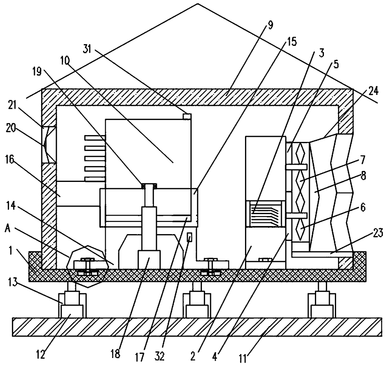
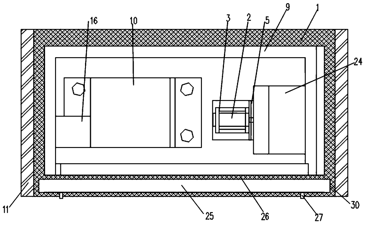
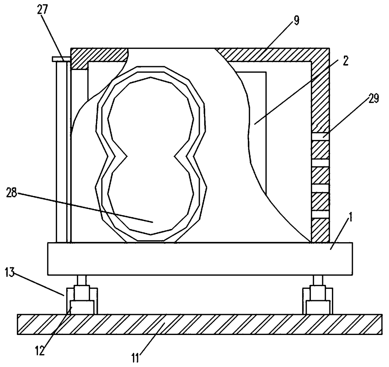
[0025] combined with figure 1 - attached Figure 9 As shown, a three-phase autotransformer includes a base 1, a three-phase autotransformer 10, a casing 9, a mounting base 11 and an air diffuser, the shell 9 is set on the upper part of the base 1, the three-phase autotransformer 10 and the air diffuser Set in the space formed by the housing 9 and the base 1, the lower end of the base 1 is fixedly connected with the lower cylinder 12, the lower end of the lower cylinder 12 is fixedly connected with the mounting seat 11, the upper end of the base 1 is slidably connected with the special-shaped slider 14 through the bolt 103, and the lower end of the bolt 103 The rectangular block 102 is connected, and the rectangular block 102 is slidably disposed in the rectangular slot 101 opened by the base 1 . The inside of the special-shaped slider 14 is a hollow structure, and an upper cylinder 18 is arranged inside the hollow structure. The upper cylinder 18 runs through the special-shap...


PUM


Abstract

The invention discloses a three-phase power autotransformer, which comprises a base, a three-phase autotransformer, a housing, a mounting base and a wind dissipation device, wherein the housing sleeves the upper part of the base; the three-phase autotransformer and the wind dissipation device are arranged in a space formed by the housing and the base; the lower end of the base is fixedly connectedwith a lower cylinder; the lower end of the lower cylinder is fixedly connected with the mounting base; the upper end of the base is connected with a special-shaped slide block through a bolt in a sliding manner; the internal part of the special-shaped slide block is of a hollow structure; an upper cylinder is arranged in the hollow structure and penetrates through the special-shaped slide block;the lower end of the upper cylinder is propped against the upper end of the base; the external part of a reinforcing bushing is fixedly connected with the three-phase autotransformer; a motor is fixedly arranged in a bracket; an output end of the motor is fixedly connected with a lower gear; a lower blade is fixed on the lower gear; the lower gear is meshed with an upper gear; and the upper gearis connected with an upper blade. The three-phase power autotransformer is capable of ensuring that the generated heat is timely transferred and dissipated, is convenient to fixedly install and simultaneously has the effect of preventing dust from being scattered on the upper edge to affect use.

Description

technical field [0001] The invention relates to the technical field of transformers, in particular to a three-phase autotransformer. Background technique [0002] Auto-coupling means electromagnetic coupling. A three-phase auto-coupling power transformer transfers energy through the electromagnetic coupling of the primary and secondary coils. The primary and secondary sides have no direct electrical connection. Auto-coupling is a three-phase auto-coupling power transformer. The secondary side has a direct electrical connection, and its low-voltage coil is a part of the high-voltage coil. [0003] In the power supply of some equipment, a three-phase auto-transformer is generally used, but a three-phase auto-transformer is different from a traditional three-phase auto-transformer. A traditional three-phase auto-transformer The appearance of the power transformer has a protective shell, which can directly dissipate heat, but the autotransformer, a kind of three-phase autotrans...

Claims


Application Information

Patent Timeline
IPC IPC(8): H01F30/02H01F30/12H01F27/02H01F27/06H01F27/08H01F27/22
CPCH01F27/02H01F27/025H01F27/06H01F27/085H01F27/22H01F30/02H01F30/12
Inventor 杨茜牛超朱振伟王东雪全磊王临铭
Owner HENAN MECHANICAL & ELECTRICAL VOCATIONAL COLLEGE
Learn More