
Display panel etching device, manufacture procedure unit and flow control method thereof

A technology for display panels and etching devices, applied in electrical components, semiconductor/solid-state device manufacturing, circuits, etc., can solve the problems of decreased etching liquid flow, high cost of use, and influence on the stability of display panel manufacturing processes, and achieves improved stability. Effect

Inactive Publication Date: 2018-09-28
WUHAN CHINA STAR OPTOELECTRONICS TECH CO LTD
View PDF4 Cites 1 Cited by
  • Summary
  • Abstract
  • Description
  • Claims
  • Application Information

AI Technical Summary

Problems solved by technology

[0004] In order to keep the flow rate of etching solution transmitted to the process chamber constant, the flow rate of etching solution transmitted through the pipeline needs to be manually adjusted through the frequency converter. Blockage and other reasons will cause a downward trend in the flow rate of etching solution
Therefore, the flow rate of the etching solution transported to the process chamber will change accordingly, and the etched structure on the display panel will be different from the preset structure, which will affect the stability of the display panel process.
In the prior art, although there are flow meters or other devices that can control the flow of pipelines, their cost is high, and it is necessary to control the flow of etching solution in the pipeline in real time without increasing the cost, so as to improve the stability of the display panel process.

Method used


Image

  • Display panel etching device, manufacture procedure unit and flow control method thereof
  • Display panel etching device, manufacture procedure unit and flow control method thereof
  • Display panel etching device, manufacture procedure unit and flow control method thereof

Examples


Embodiment Construction

[0013] The following will clearly and completely describe the technical solutions in the embodiments of the application with reference to the drawings in the embodiments of the application. Apparently, the described embodiments are only some of the embodiments of the application, not all of them. Based on the embodiments in this application, all other embodiments obtained by persons of ordinary skill in the art without making creative efforts belong to the scope of protection of this application.

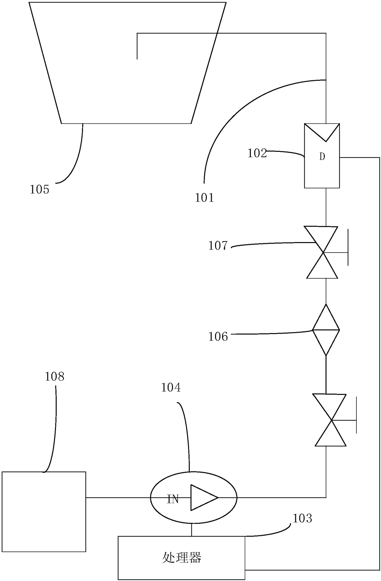
[0014] see figure 1 , figure 1 It is a structural schematic diagram of an embodiment of the process unit of the present application.

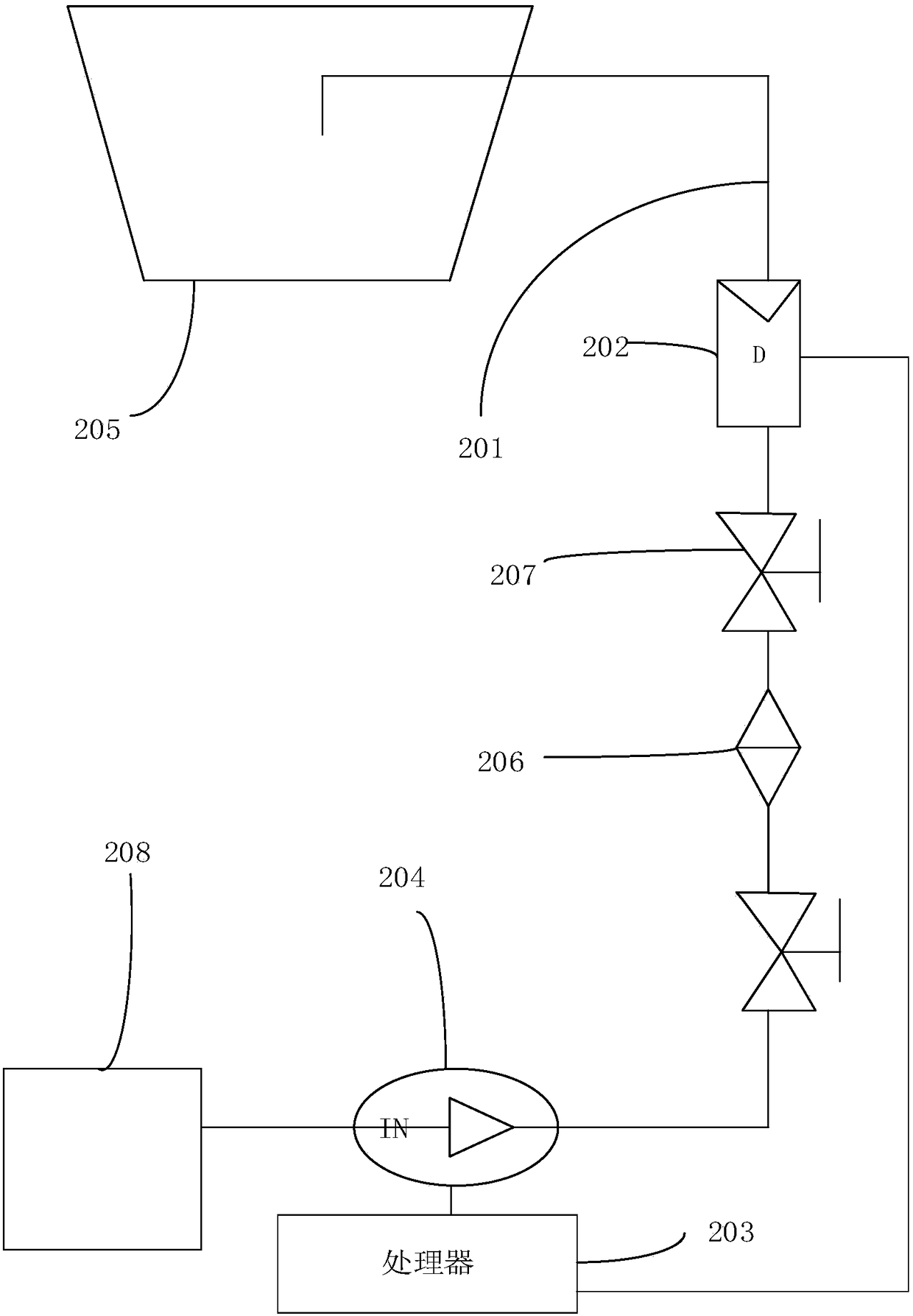
[0015] The embodiment of the present application provides a process unit, including: a pipeline 101 , a nozzle (not shown), a flow meter 102 , a processor 103 , a variable frequency pump 104 , a process chamber 105 and a filter 106 .

[0016] A process unit (not shown) transmits an etching solution that can be used for etching on the display panel ...


PUM


Abstract

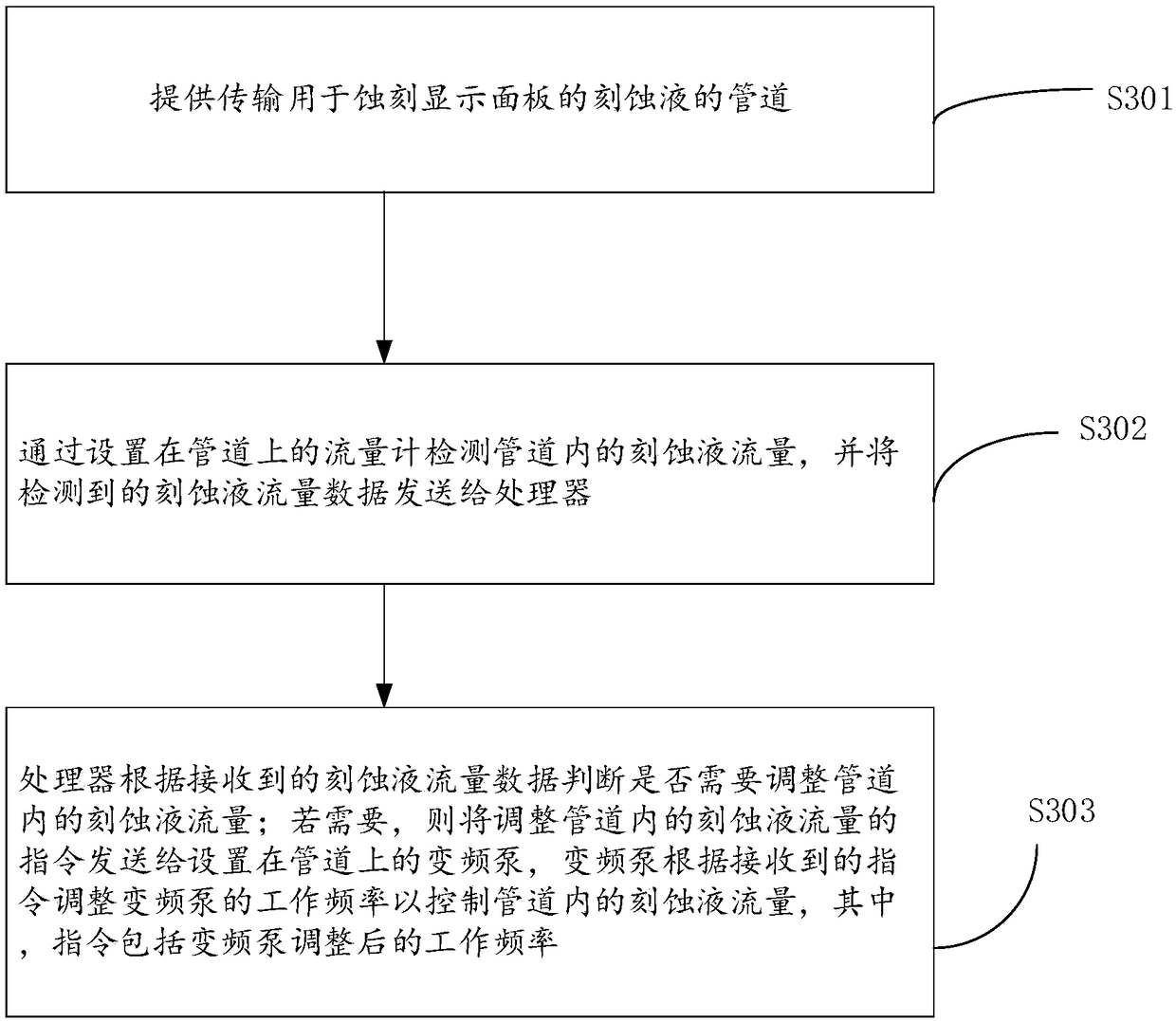
The application provides a display panel etching device, a manufacture procedure unit and a flow control method thereof. The manufacture procedure unit comprises a pipeline; a sprayer located at one end of the pipeline; a flowmeter arranged on the pipeline; a processor respectively connected with a variable frequency pump and the flowmeter, wherein the processor is used for acquiring etching liquid flow data transmitted by the flowmeter in the pipeline, and sending an instruction for adjusting the etching liquid flow in the pipeline to the variable frequency pump according to the flow data; the variable frequency pump arranged on the pipeline, wherein the variable frequency pump is far away from the sprayer with respect to the flowmeter, and is used for adjusting the working frequency of the variable frequency pump according to the received instruction, thereby adjusting the flow of the pipeline; the instruction comprises the adjusted working frequency of the variable frequency pump. Under the condition of not increasing the cost, the etching liquid flow in the pipeline can be controlled timely, and the stability of the manufacture procedure of the display panel is improved.

Description

technical field [0001] The present application relates to the field of display panel manufacturing, in particular to a display panel etching device, a process unit and a flow control method thereof. Background technique [0002] Liquid crystal display panels and organic light-emitting display panels are the two most widely used display panels at present. They have the advantages of low power consumption, thin and light weight, and low-voltage drive. They can be used in personal computers, file processors, navigation systems, and game consoles. , projectors, viewfinders (view finder) and various electronic devices in life, such as: watches, electronic computers, televisions, etc. [0003] In the manufacturing process of the liquid crystal display panel and the organic light-emitting display panel, in order to form a circuit for driving pixels to emit light and to form a preset structure, it is necessary to form a preset structure on the display panel by etching. However, in ...

Claims


Application Information

Patent Timeline
IPC IPC(8): H01L21/67
CPCH01L21/6708H01L21/67253
Inventor 何军
Owner WUHAN CHINA STAR OPTOELECTRONICS TECH CO LTD
Learn More