
Motor rotor iron core potting lamination device and potting method

A pressing device and rotor core technology, which is applied in electromechanical devices, manufacturing motor generators, manufacturing stator/rotor bodies, etc., can solve the problems of reducing and easily entering the performance of the rotor core between the core punching sheets, and achieve The overall structure is simple, the effect of locking and pressing is good, and the effect of preventing axial movement

Active Publication Date: 2018-09-28
江苏金坛绿能新能源科技有限公司 +1
View PDF8 Cites 8 Cited by
  • Summary
  • Abstract
  • Description
  • Claims
  • Application Information

AI Technical Summary

Problems solved by technology

[0004] In order to solve the above-mentioned technical problems, the present invention provides a motor rotor iron core glue filling and pressing device and glue filling method, which solves the problem that when the rotor iron core uses potting glue to fix the magnetic steel, the glue is easy to enter between the iron core punching pieces and cause problems. For the problem of reducing the performance of the rotor core, by designing a motor rotor core glue filling and pressing device, the punching pieces of the rotor core can be quickly pressed and positioned and locked, eliminating the gap between the punching pieces and blocking the The possibility of potting glue entering between the punching sheets improves the performance of the rotor core, and is easy to assemble and disassemble, improving work efficiency

Method used


Image

  • Motor rotor iron core potting lamination device and potting method
  • Motor rotor iron core potting lamination device and potting method

Examples


Embodiment Construction

[0029] The specific implementation manner of the present invention will be described in further detail below by describing the best embodiment with reference to the accompanying drawings.

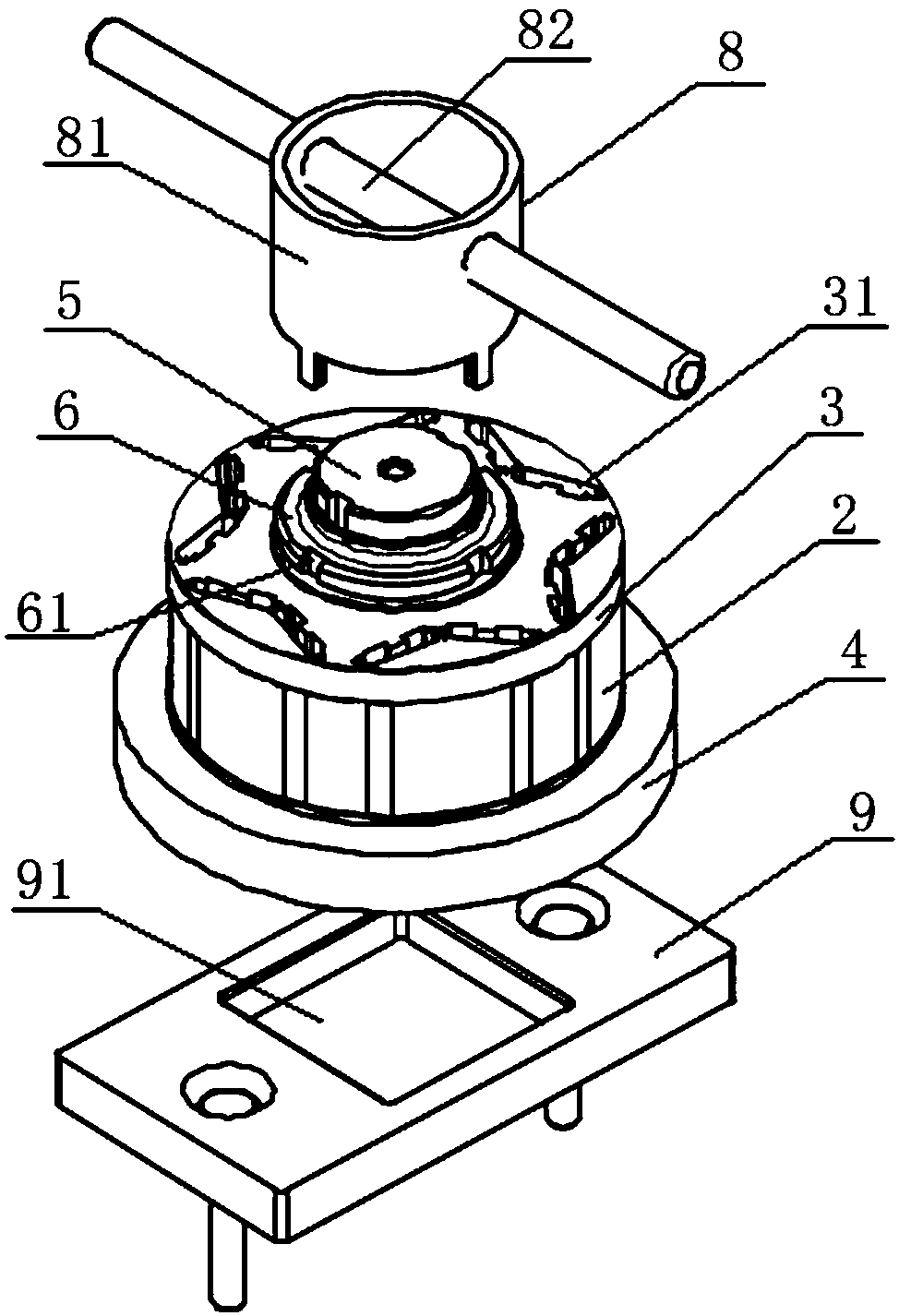
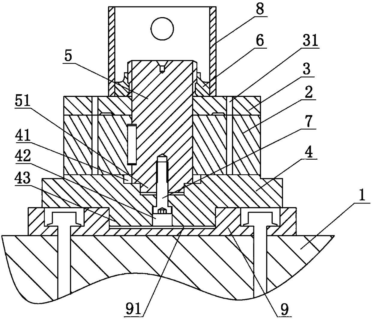
[0030] Concrete embodiment of the present invention is: as figure 1 , figure 2 As shown, a motor rotor core glue filling and pressing device is placed on the operating platform 1, including a cover plate 3 and a base 4 respectively arranged on the upper and lower end faces of the rotor core 2, and positioned in the rotor core 2 and The cover plate 3 and the base 4 are locked and connected to the connecting shaft 5. The cover plate 3 is provided with a glue injection groove 31 communicating with the magnetic steel groove of the rotor core 2. The notch area of ​​the glue injection groove 31 is not larger than the magnetic steel groove The area of ​​the notch avoids the unevenness of the end surface of the rotor core 2 caused by the potting glue flowing to the end surface of the rotor core 2...


PUM


Abstract

The invention relates to a motor rotor iron core potting lamination device and a potting method, and belongs to the technical field of a motor rotor. The lamination device is placed on an operation platform and comprises a cover board and a base which are respectively arranged on the upper and lower end faces of a rotor iron core, and a connection shaft which is positioned in the rotor iron core and locks and connects the cover board and the base; and an adhesive injection groove communicated with a magnetic steel groove of the rotor iron core is formed on the cover board. The potting method applying the lamination device comprises: installation of the potting lamination device, injection of a potting adhesive, curing of the potting adhesive and disassembling of a locking structure. The motor rotor iron core potting lamination device and the potting method have the beneficial effects that the potting lamination device is simple in structure, convenient and rapid to operate and convenient for integral assembling, locking and disassembling, and can effectively solve a problem that after the rotor iron core is injected with the adhesive, the adhesive permeates into a gap between punching sheets; use performance of the rotor iron core is improved; and working efficiency is improved.

Description

technical field [0001] The invention relates to the technical field of motor rotors, in particular to a glue filling and pressing device and a glue filling method for an iron core of a motor rotor. Background technique [0002] At present, with the rapid development of the new energy vehicle industry, as one of the three core components of new energy vehicles, the design of the motor, especially the permanent magnet synchronous motor, has received more and more attention within the industry. The core generally adopts the embedded type of magnetic steel. Since the magnetic steel is a clearance fit, the fixing of the magnetic steel has become the focus of the permanent magnet synchronous motor. [0003] Fixing of magnetic steel At present, the fixing methods on the market mainly include bonding and fixing of anaerobic glue, potting and fixing of glue, and injection molding of the gap between magnetic steel and steel by injection molding machine. The fixing method of anaerobic ...

Claims


Application Information

Patent Timeline
Patent Type & Authority Applications(China)
IPC IPC(8): H02K15/03
CPCH02K15/03
Inventor 吴建中张晓东吴潇朱琛琦张新曹远洲
Owner 江苏金坛绿能新能源科技有限公司
Learn More