
Transducer having a conductive suspension member

A technology of transducers and components, applied in the direction of electrical components, sensors, loudspeakers, etc., can solve problems such as wire breakage

Active Publication Date: 2018-09-28
APPLE INC
View PDF5 Cites 8 Cited by
  • Summary
  • Abstract
  • Description
  • Claims
  • Application Information

AI Technical Summary

Problems solved by technology

However, due to strain on these leads caused by diaphragm deflection, the wires can break, eventually leading to reliability issues in the field

Method used


Image

  • Transducer having a conductive suspension member
  • Transducer having a conductive suspension member
  • Transducer having a conductive suspension member

Examples


Embodiment Construction

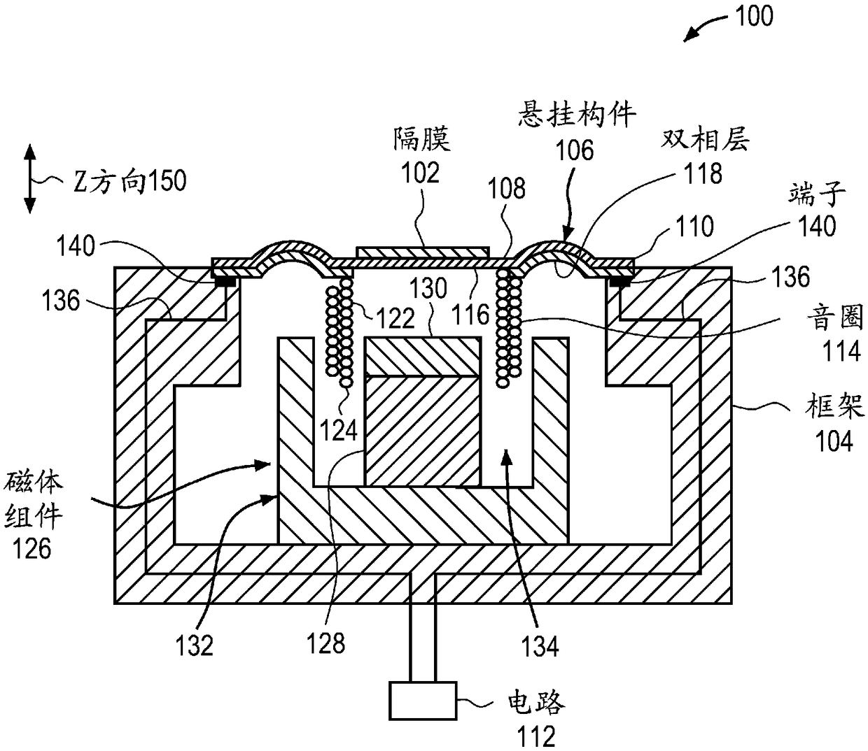
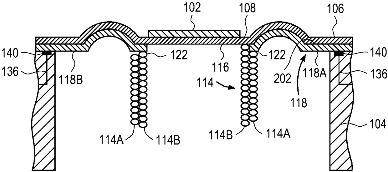
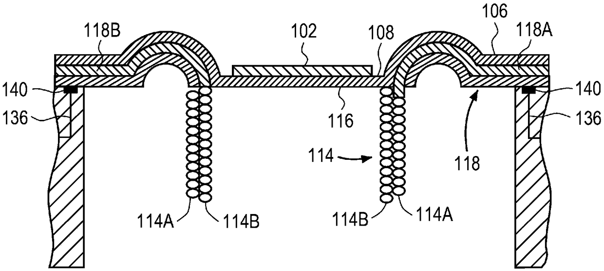
[0022] In this section, we will explain several preferred embodiments of the invention with reference to the accompanying drawings. Whenever the shapes, relative positions, and other aspects of components described in the embodiments are not clearly defined, the scope of the present invention is not limited only to the illustrated components, which are for illustration purposes only. Additionally, while numerous details are set forth, it is understood that some embodiments of the invention may be practiced without these details. In other instances, well-known structures and techniques have not been shown in detail in order not to obscure the understanding of this description.

[0023] figure 1A cross-sectional side view of one embodiment of a transducer is shown. The transducer 100 may be, for example, an electroacoustic transducer that converts an electrical signal into an audible signal that can be output from a device in which the transducer 100 is integrated. For exampl...


PUM


Abstract

A speaker including a frame, and a magnet assembly coupled to the frame. The magnet assembly forms an air gap through which a magnetic flux is directed. The speaker further including a voice coil suspended in the air gap, a diaphragm coupled to the voice coil and a compliant suspension member for suspending the voice coil within the air gap. The suspension member includes an electrically conductive biphasic member for providing an electrical connection between the voice coil and a circuit coupled to the frame.

Description

technical field [0001] One embodiment of the invention relates to a transducer, such as a loudspeaker, having a compliant suspension member that provides an electrical connection between a voice coil and the electrical terminals of the transducer. Other embodiments are also described and claimed. Background technique [0002] In modern consumer electronics, audio functionality is playing an increasing role as digital audio signal processing and audio content delivery continue to improve. In this regard, a wide range of consumer electronic devices could benefit from improvements in audio performance. For example, smartphones include, for example, electromechanical transducers that convert electrical audio signals into corresponding sounds. More specifically, horn amplifiers and earpiece receivers can benefit from improved audio performance. However, smartphones don't have enough room for larger high-fidelity sound output devices. This is true for some portable personal co...

Claims


Application Information

Patent Timeline
Patent Type & Authority Applications(China)
IPC IPC(8): H04R1/06H04R9/02H04R7/08H04R9/04H04R7/20
CPCH04R9/045H04R7/08H04R9/02H04R9/06H04R1/06H04R2400/11H04R7/20H04R9/047H04R2499/11H04R2307/204
Inventor A·V·萨尔瓦蒂
Owner APPLE INC
Learn More