

Radon gas removing device and method
A technology of radon gas and pressurized chamber, applied in the field of radon gas removal device, can solve the problems of low efficiency, difficult to control cost, difficult to completely reduce indoor radon content, etc.
- Summary
- Abstract
- Description
- Claims
- Application Information
AI Technical Summary
Problems solved by technology
Method used
Image

Examples
Embodiment 1
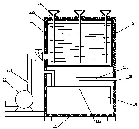
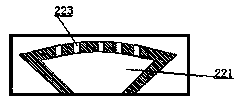
[0032] This embodiment provides a radon gas removal device, such as figure 1 and figure 2 , including a casing 1, including a spray assembly, the spray assembly includes a pressurized chamber 21 for holding liquid and a plurality of spray nozzles 22; the pressurized chamber 21 is fixed in the casing 1 (in this embodiment, The pressurized chamber is a high-pressure tank, and the casing is an aluminum alloy casing that is turned and stamped, and the pressurized chamber is welded in the casing); the spray nozzle 22 is fixed on the top of the casing 1; the spray nozzle 22 includes an inverted cone The buffer chamber 221, the top of the buffer chamber 221 communicates with the pressurized chamber 21 through a conduit 222, and the conduit 222 extends below the liquid level of the pressurized chamber 21; the bottom of the buffer chamber 221 is provided with a spray hole 223; in this embodiment Among them, the spray nozzle is plastic injection molding; the pressurized chamber 21 is ...
Embodiment 2
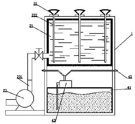
[0036] This embodiment provides a radon gas removal device, such as image 3 and Figure 4 , 5 , including a casing 1, including a spray assembly, the spray assembly includes a pressurized chamber 21 for holding liquid and a plurality of spray nozzles 22; the pressurized chamber 21 is fixed in the casing 1 (in this embodiment, The pressurized chamber is a high-pressure tank, and the casing is an aluminum alloy casing that is turned and stamped, and the pressurized chamber is welded in the casing); the spray nozzle 22 is fixed on the top of the casing 1; the spray nozzle 22 includes an inverted cone The buffer chamber 221, the top of the buffer chamber 221 communicates with the pressurized chamber 21 through a conduit 222, and the conduit 222 extends below the liquid level of the pressurized chamber 21; the bottom of the buffer chamber 221 is provided with a spray hole 223; in this embodiment Among them, the spray nozzle is plastic injection molding; the pressurized chamber 2...
Embodiment 3
[0040] This embodiment provides a radon gas removal device, such as Figure 6, including a casing 1, including a spray assembly, the spray assembly includes a pressurized chamber 21 for holding liquid and a plurality of spray nozzles 22; the pressurized chamber 21 is fixed in the casing 1 (in this embodiment, The pressurized chamber is a high-pressure tank, and the casing is an aluminum alloy casing that is turned and stamped, and the pressurized chamber is welded in the casing); the spray nozzle 22 is fixed on the top of the casing 1; the structure of the spray nozzle is the same as in Example 1 Consistent; the pressurized chamber 21 is also connected with an air pump 23 , and the inflation port 231 of the air pump 23 communicates with the pressurized chamber 21 . In this embodiment, a fixed plate 11 is welded outside the casing, and the air pump 23 is placed on the fixed plate. In this embodiment, a check valve is also provided between the air pump and the pressurized chamb...
PUM
 Abstract
Description
Claims
Application Information