Fuse box mounting structure

A technology of fuse box and installation structure, applied in emergency protection devices, electrical components, circuits, etc., can solve the problems of inconvenient operation and low installation efficiency, and achieve the effect of improving production efficiency, reducing design requirements and reducing production costs

Inactive Publication Date: 2018-10-02
ZHEJIANG LEAPMOTOR TECH CO LTD
View PDF5 Cites 0 Cited by
  • Summary
  • Abstract
  • Description
  • Claims
  • Application Information

AI Technical Summary

Problems solved by technology

The hand holding the fuse box also needs to be used to position the bolts during operation, resulting in very inconvenient operation and low installation efficiency

Method used


Image

  • Fuse box mounting structure
  • Fuse box mounting structure
  • Fuse box mounting structure

Examples


Embodiment Construction

[0020] The present invention will be further described below in conjunction with the accompanying drawings and specific embodiments.

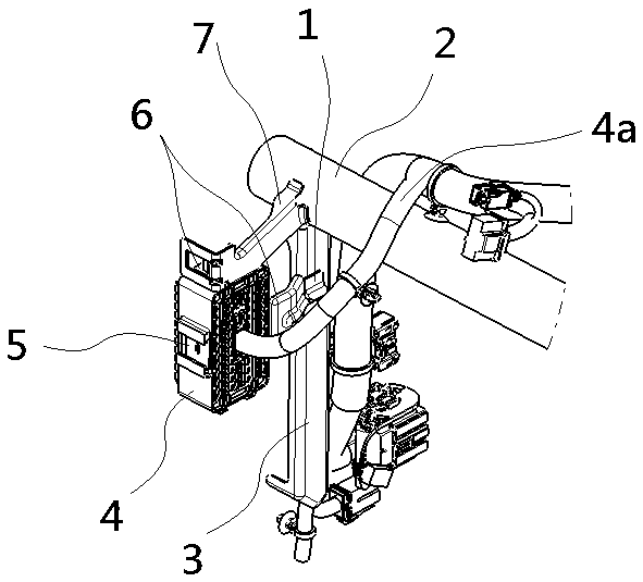
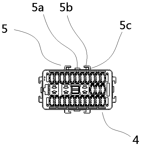
[0021] Such as figure 1 In the shown embodiment, a fuse box installation structure includes a fuse box 4 and an instrument panel main beam 2. The instrument panel main beam is a straight tube structure, which effectively reduces the overall weight and is conducive to realizing the lightweight of the vehicle. The main beam of the instrument panel is arranged horizontally, and the fuse box is arranged at one end of the main beam of the instrument panel.

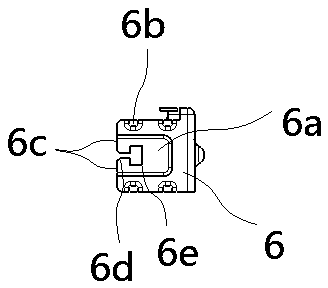
[0022] A first installation bracket 7 and a second installation bracket 1 are provided on the main beam of the instrument panel, and buckle seats 6 are respectively provided at the outer ends of the first installation bracket and the second installation bracket. The first mounting bracket is welded to the end of the main beam of the instrument panel, the first mounting bracket is fixed on a hor...


PUM


Abstract

The invention discloses a fuse box mounting structure which comprises a fuse box and an instrument panel main pipe beam. At least two side surfaces of the instrument panel main pipe beam and the fusebox are respectively provided with a buckle. The instrument panel main beam is provided with a first mounting bracket and a second mounting bracket. The outer end of the first mounting bracket and theouter end of the second mounting bracket are respectively provided with a buckle seat. The buckle seat is provided with a buckle hole. The buckle is in snapping matching with the buckle hole. The invention aims to provide the fuse box mounting structure which reduces a designing requirement and facilitates assembling.

Description

technical field [0001] The invention belongs to the field of new energy vehicles, and in particular relates to a fuse box installation structure. Background technique [0002] With the development of new energy vehicles, intelligence and transportation have become the development trend of the automobile industry, which requires more electrical units to be added to the car. In order to protect the lives and properties of drivers and passengers, many electrical units require fuse boxes to ensure the normal operation of the vehicle. At present, fuse boxes are generally borrowed parts. Since the layout position of the main beam of the instrument panel has been determined in the early stage, the design of the beam bracket of the instrument panel is relatively difficult. In the actual design process, the design of the instrument panel beam bracket is often complicated due to the influence of the fuse box layout, and the cost of the instrument panel beam bracket will increase acco...

Claims


Application Information

Patent Timeline
Patent Type & Authority Applications(China)
IPC IPC(8): H01H85/20
CPCH01H85/2045
Inventor 宋金强杨学舟龙刚启
Owner ZHEJIANG LEAPMOTOR TECH CO LTD
Why Eureka
Try Eureka