Calibration device of self-adaption optical system based on far field performance indexes

A technology of adaptive optics and system calibration, applied in measuring devices, measuring optics, optical radiation measurement, etc., can solve the problems of increasing the requirements of optical device processing technology, unsatisfactory spot distribution, and inability to fully reflect the advantages of adaptive optics. The operation process is simple and the correction effect is improved

Inactive Publication Date: 2010-06-02
INST OF OPTICS & ELECTRONICS - CHINESE ACAD OF SCI
View PDF0 Cites 17 Cited by
  • Summary
  • Abstract
  • Description
  • Claims
  • Application Information

AI Technical Summary

Problems solved by technology

However, since the calibration optical path does not involve the aberrations of the subsequent optical path of the wavefront detector, especially the aberrations other than defocus at the imaging lens, even if the aberrations in front of the detector are fully corrected, the spot distribution detected at the imaging position still not ideal
In some occasions such as inertial confinement fusion (ICF) devices, there are several other optical devices from the position where the wavefront detector (Hartmann sensor) is placed to the far-field imaging position (shooting range). It is also difficult to guarantee a good result for the spot distribution obtained at
Under this premise, in order to obtain a better spot distribution in the target field, it is necessary to improve the image quality of the optical device in the subsequent optical path of the wavefront detector and increase the requirements for the processing technology of the optical device, which cannot fully reflect the advantages of adaptive optics
[0003] Domestic Dai Wanjun et al pointed out the influence of different adaptive optics calibration methods on the wavefront correction of a large laser prototype in the literature "High-power solid-state laser device Hartmann sensor reference wavefront calibration method", but the proposed calibration method Mainly for this large laser prototype device, not generalizable for general adaptive optics systems

Method used


Image

  • Calibration device of self-adaption optical system based on far field performance indexes
  • Calibration device of self-adaption optical system based on far field performance indexes
  • Calibration device of self-adaption optical system based on far field performance indexes

Examples


Embodiment Construction

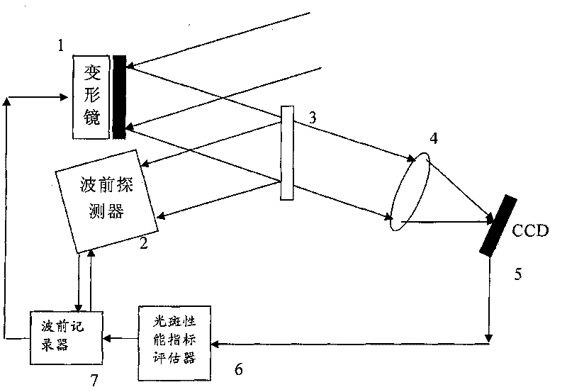
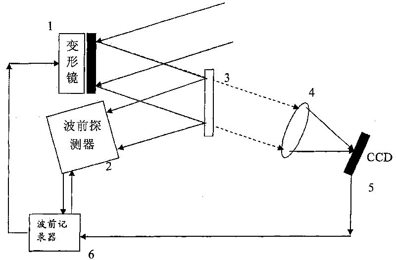
[0019] Such as figure 1 As shown, after the calibration beam passes through the wavefront corrector 1, it is divided into two paths by the half mirror 3, one path enters the wavefront detector 2, and the other path converges on the CCD detector 5 through the imaging lens 4, and the spot performance index evaluator 6 Receive the output results of the CCD detector 5, calculate the performance parameters of the light spot and perform closed-loop control on the wavefront corrector 1, so that the performance parameters calculated by the final light spot performance index evaluator 6 reach the predetermined optimal value, and the performance parameters is the mean radius (MR), or Strebe ratio (SR), or the square sum of light intensity (EE) index, in is the light intensity distribution of the spot detected by the CCD, is the light intensity value at the coordinate origin, is the light intensity value at the origin of coordinates when the incident beam does not contain aber...


PUM


Abstract

The invention discloses a calibration device of a self-adaption optical system based on far field performance indexes, which comprise a self-adaption optical system, a facula performance index estimator and a wavefront recorder. A light beam firstly passes through a traditional self-adaption optical system and then converges on an imaging focal plane; the facula performance index estimator (detects) computes light beam quality on the focal plane and outputs a corresponding performance index; a wavefront corrector in the self-adaption optical system is controlled to close loop according to the output performance index so as to enable the performance index output by the facula performance index estimator to reach a preset target; and finally the wavefront recorder records wavefront data of the wavefront detector in the self-adaption optical system when achieving the preset target, and takes the recorded wavefront data of the wavefront detector as a final target of the closed loop of the self-adaption optical system. By taking the facula at the imaging focal plane as a correction standard, consequent light paths of the wavefront detector and in particular design requirements on an imaging lens can be reduced, and the correction effect of the self-adaption optics can be improved.

Description

technical field [0001] The invention relates to a calibration device for an adaptive optics system, in particular to a calibration device for an adaptive optics system based on a far-field performance index. Background technique [0002] At present, in the systems that use the adaptive optics system for phase correction, the adaptive optics system needs to be calibrated before the closed-loop control, and the incident phase difference is closed-looped with the calibration data as the target. However, since the calibration optical path does not involve the aberrations of the subsequent optical path of the wavefront detector, especially the aberrations other than defocus at the imaging lens, even if the aberrations in front of the detector are fully corrected, the spot distribution detected at the imaging position Still not ideal. In some occasions such as inertial confinement fusion (ICF) devices, there are several other optical devices from the position where the wavefront ...

Claims


Application Information

Patent Timeline
Patent Type & Authority Applications(China)
IPC IPC(8): G01J9/00G01J9/02
Inventor 黄林海饶长辉姜文汉
Owner INST OF OPTICS & ELECTRONICS - CHINESE ACAD OF SCI
Why Eureka
Try Eureka