Master-slave point-by-point correcting method for LED display screen

An LED display, point-by-point correction technology, applied in static indicators, instruments, etc., can solve problems such as unsatisfactory correction results

Active Publication Date: 2011-01-19
滁州一银丰新材料有限公司
View PDF9 Cites 28 Cited by
  • Summary
  • Abstract
  • Description
  • Claims
  • Application Information

AI Technical Summary

Problems solved by technology

[0013] On-site application is limited, because the LED display screen 1 is often used in a higher position, and the imaging device 2 is generally placed far away from the display screen (tens of meters), one is because of the imaging effect of the imaging device, and the other is Because of on-site obstacles, the imaging device 2 must be placed far away, so tha

Method used


Image

  • Master-slave point-by-point correcting method for LED display screen
  • Master-slave point-by-point correcting method for LED display screen
  • Master-slave point-by-point correcting method for LED display screen

Examples


Embodiment 1

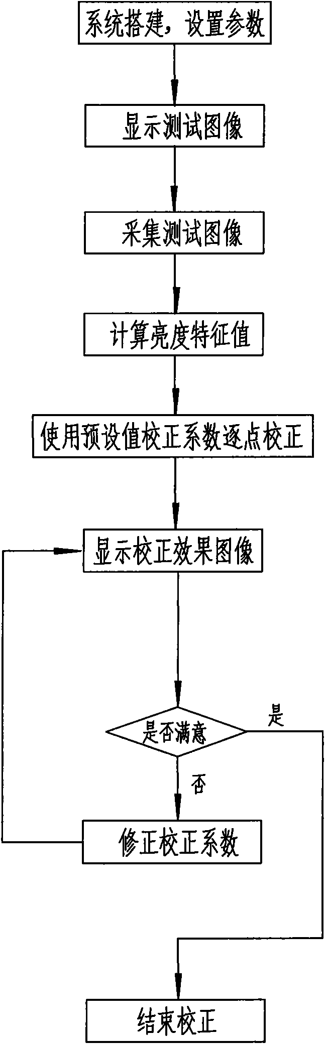
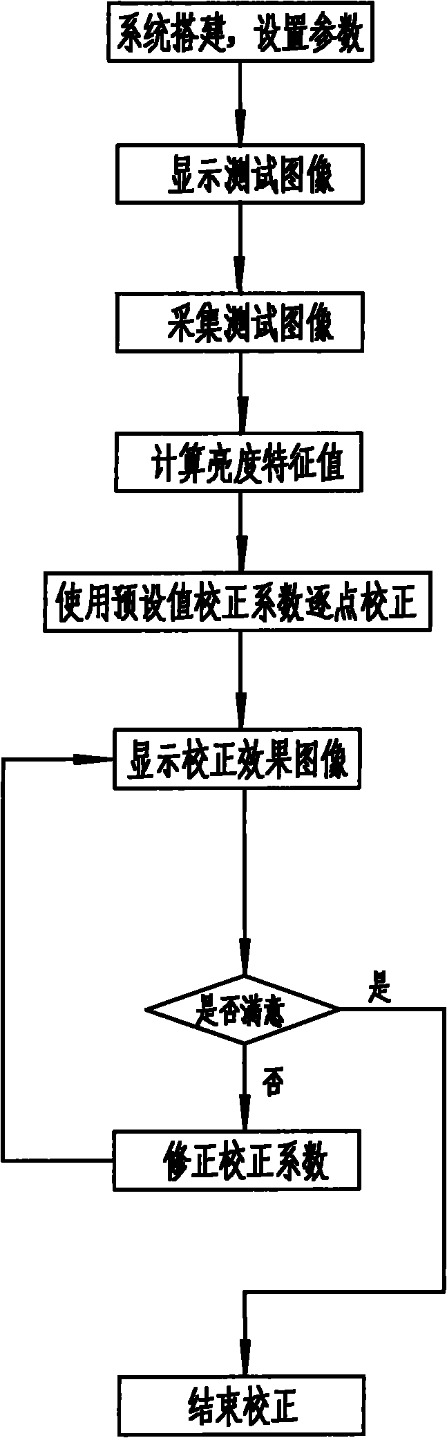
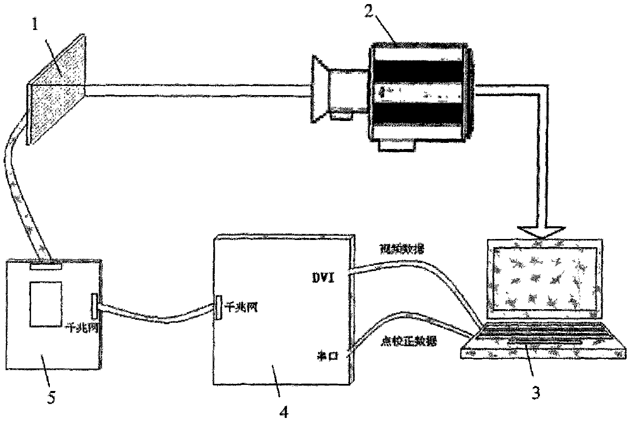
[0036] Such as Figure 4 Shown is the flow chart of the method of the present invention, the present embodiment provides a kind of LED display screen point-by-point correction method of master-slave mode, first combines figure 2 The point-by-point correction system of the LED display screen in the master-slave mode is described in detail. The system structure includes: a master control module 10, a slave control module 14, an image acquisition device 12, a wireless transmitting module 11, a wireless receiving module 13 and an LED display screen 15; the main control module 10 is connected with the image acquisition device 12 and the wireless transmission module 11, the main control module 10 controls the image acquisition device 12 to collect the test image displayed on the LED display screen 15, and obtains each LED light point in the test image According to the brightness characteristic value of the system preset correction coefficient, the adjusted lamp point brightness dat...

Embodiment 2

[0051] Yet another example, such as image 3 As shown, in the above-mentioned point-by-point correction system, the main control module 10 also includes an image acquisition control unit 103, a data processing unit 101 and a wireless transmission control unit 104 connected in sequence; the image acquisition control unit 103 is connected with the image acquisition device 12 for Collect the test image by controlling the image acquisition device 12; the data processing unit 101 is used to receive the test image, process the test image to obtain the brightness data of the lamp point; the wireless transmission control unit 104 is connected with the wireless transmission module 11, and uses To control the wireless transmitting module 11 to send commands and the brightness data of the lamps to the wireless receiving module 13 .

[0052] Yet another example, such as image 3 As shown, the main control module 10 also includes a user input unit 105 for inputting parameters of the LED d...


PUM


Abstract

The invention discloses a master-slave point-by-point correcting method for an LED display screen, which comprises a master control end and a slave control end, and comprises the following steps: A1, the master control end transmits a command to the slave control end, and the slave control end controls the LED display screen to display a test image according to the command; A2, an image acquiring device is utilized to acquire the test image while the test image is displayed; A3, the luminance characteristic value of LED lamp spots in the test image is calculated; A4, the adjusted lamp spot luminance data is calculated according to the correction coefficient preset by the system, and the master control end transmitts the lamp spot luniance data to the slave control end; A5, the LED display screen is controlled to display a corrected effect image according to the lamp spot luminance data; and A6, according to the corrected image, correcting the preset correction coefficient until the satisfied effect is obtained.

Description

technical field [0001] The invention relates to the technical field of LED display, in particular to a point-by-point correction method of an LED display screen in a master-slave mode. Background technique [0002] With the mass application of various public information media, people can choose different display media to carry information, such as neon lights, printed advertising boards, three-sided flip advertising boards, PDP TV walls, etc. However, the above-mentioned display media all have defects such as limited display content or unsatisfactory brightness and effect. With the continuous improvement of user requirements for the performance of display devices for large-screen display media indoors and outdoors in terms of color, brightness, video effects, reliability, and lifespan, the display system is required to display true-color images that are close to natural colors, and It has a high display brightness, so that the display system can let the audience see the dis...

Claims


Application Information

Patent Timeline
IPC IPC(8): G09G3/00G09G3/32
Inventor 邵寅亮伍更新罗瑶李伟
Owner 滁州一银丰新材料有限公司
Why Eureka
Try Eureka