Image capturing apparatus, method of controlling the same, and storage medium

Active Publication Date: 2014-07-03
CANON KK
View PDF6 Cites 29 Cited by
  • Summary
  • Abstract
  • Description
  • Claims
  • Application Information

AI Technical Summary

Benefits of technology

[0007]The present invention has been made in consideration of the above-described problems, and provides an image capturing apparatus which can correctly per

Problems solved by technology

In recent years, along with a decrease in size of an image capturing apparatus and an increase in magnification of an optical system, a shake of an image capturing apparatus or the like becomes a large factor which reduces the quality of a shot image.
In the image blurring correction function, if the movement of an image by a panning operation performed by a photographer to intentionally change the shooting range of the image capturing apparatus is corrected, the panning operation by the photographer is unwantedly hindered.
T

Method used


Image

  • Image capturing apparatus, method of controlling the same, and storage medium
  • Image capturing apparatus, method of controlling the same, and storage medium
  • Image capturing apparatus, method of controlling the same, and storage medium

Examples


first embodiment

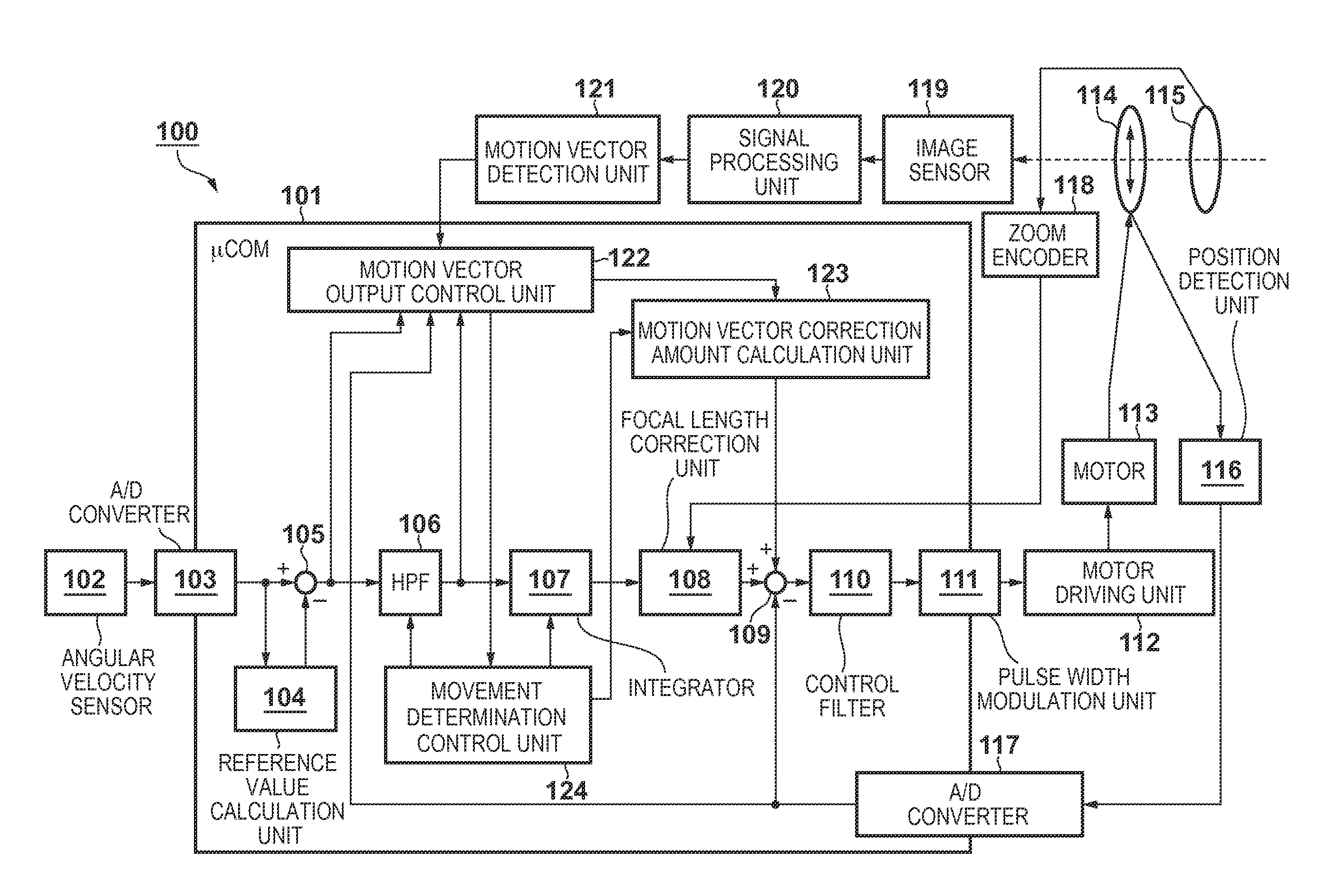
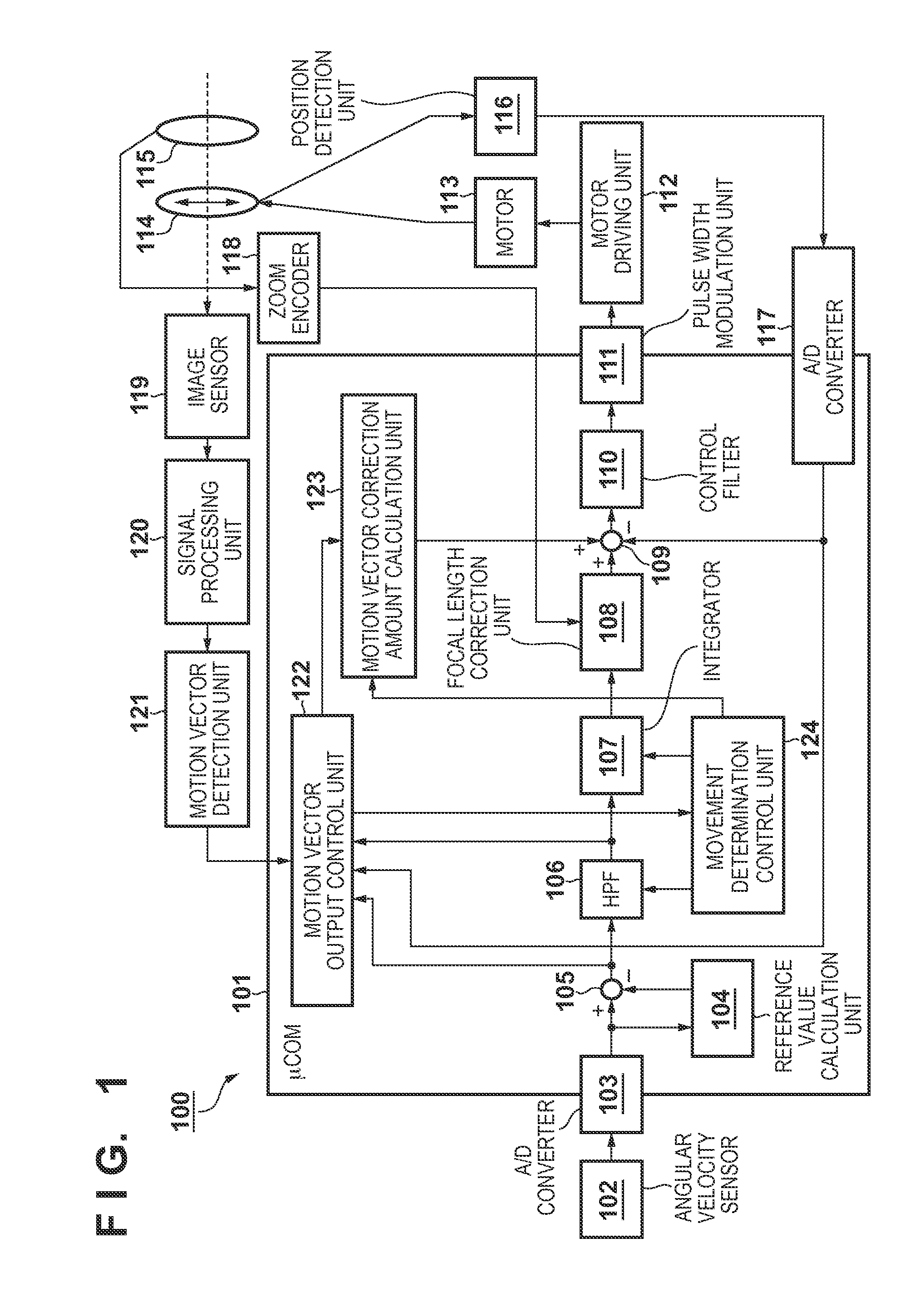
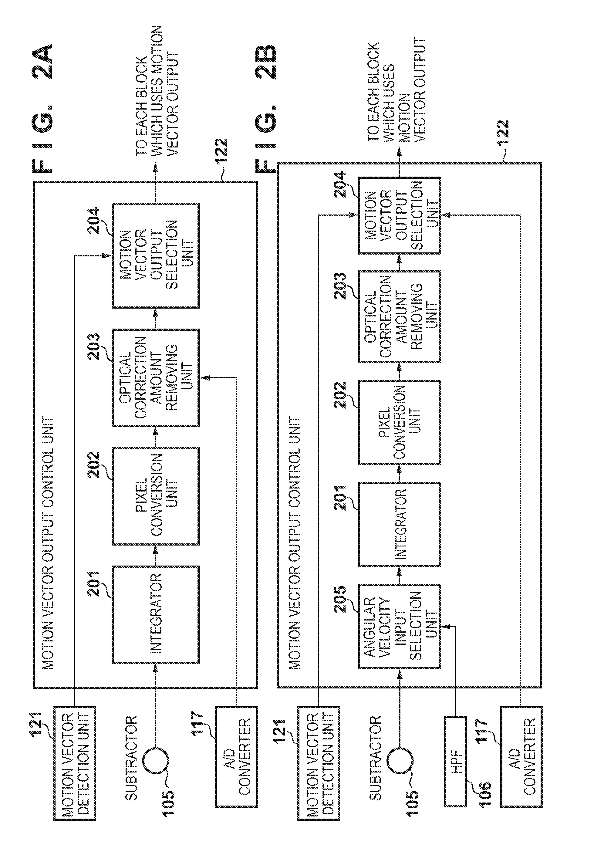
[0036]FIG. 2A is a block diagram showing the arrangement of a motion vector output control unit 122 according to the first embodiment. The operation of the motion vector output control unit 122 will be described in detail below. Note that the same components as those shown in FIG. 1 have the same reference numerals and a description thereof will be omitted.

[0037]The motion vector output control unit 122 calculates an output (to be referred to as an angular velocity moving amount hereinafter) equivalent to a motion vector detection result using the output of an angular velocity sensor 102. The motion vector output control unit 122 has a function of outputting the angular velocity moving amount instead of the output of a motion vector detection unit 121 if it is estimated that the motion vector detection result of the motion vector detection unit 121 is incorrect.

[0038]An integrator 201, a pixel conversion unit 202, and an optical correction amount removing unit 203 are blocks for cal...

second embodiment

[0067]FIG. 2B is a block diagram showing the arrangement of a motion vector output control unit 122 according to the second embodiment. The operation of the motion vector output control unit 122 will be described in detail below. Note that the same components as those shown in FIGS. 1 and 2A have the same reference numerals and a description thereof will be omitted.

[0068]FIG. 2B is a block diagram in which an angular velocity input selection unit 205 is added before an integrator 201, as compared with FIG. 2A. The angular velocity input selection unit 205 selects one of the output of a subtractor 105 and that of an HPF 106, and supplies the selected output to the integrator 201.

[0069]FIG. 8 is a flowchart illustrating a processing procedure executed by the angular velocity input selection unit 205. In step S100, the angular velocity input selection unit 205 determines whether a reference value calculation unit 104 has calculated a reference value at least once after power-on of an i...


PUM


Abstract

An image capturing apparatus comprises a shake detection unit configured to detect a shake, a motion vector detection unit configured to detect a motion vector indicating movement of an image from a captured image signal, a motion vector output control unit configured to selectively output an output of the motion vector detection unit and an output of the shake detection unit, a correction amount calculation unit configured to calculate a shake correction amount based on at least one of the output of the motion vector output control unit and the output of the shake detection unit; and a correction unit configured to correct the image blurring of the captured image based on the shake correction amount.

Description

BACKGROUND OF THE INVENTION[0001]1. Field of the Invention[0002]The present invention relates to a technique of mechanically or electronically correcting image blurring of a shot image caused by a shake of an image capturing apparatus.[0003]2. Description of the Related Art[0004]In recent years, along with a decrease in size of an image capturing apparatus and an increase in magnification of an optical system, a shake of an image capturing apparatus or the like becomes a large factor which reduces the quality of a shot image. In this regard, various image blurring correction functions of correcting image blurring of a captured image caused by a shake of an apparatus or the like are proposed.[0005]In the image blurring correction function, if the movement of an image by a panning operation performed by a photographer to intentionally change the shooting range of the image capturing apparatus is corrected, the panning operation by the photographer is unwantedly hindered. The present a...

Claims


Application Information

Patent Timeline
IPC IPC(8): H04N5/232
CPCH04N5/23254H04N5/23264H04N23/682H04N23/6811H04N23/685H04N23/6812H04N23/6815
Inventor MIYASAKO, KENICHI
Owner CANON KK
Why Eureka
Try Eureka