
Digital control drilling machine protection device

A technology of CNC drilling machine and protective device, which is applied in the direction of drilling/drilling equipment, maintenance and safety accessories, parts of boring machine/drilling machine, etc., which can solve the problems of personal injury, short service life and serious wear and tear of workers, To achieve the effect of improving integrity and efficiency, avoiding mutual interference, and high operating efficiency

Inactive Publication Date: 2018-10-09
王秀兰
View PDF0 Cites 2 Cited by
  • Summary
  • Abstract
  • Description
  • Claims
  • Application Information

AI Technical Summary

Problems solved by technology

[0002] Drilling machine refers to the general name of machinery and equipment that leaves cylindrical holes or holes on the target by means of rotary cutting or rotary extrusion with a tool that is harder and sharper than the target. Machines, drilling machines, through-hole machines, etc., achieve the desired effect by drilling precision parts. Drilling machines include semi-automatic drilling machines and fully automatic drilling machines. With the increase in human resource costs; most enterprises Both consider fully automatic drilling machines as the development direction. With the development of the times and the improvement of the drilling technology of automatic drilling machines, fully automatic drilling machines are used to drill holes for various metal molds, watch straps, watch straps, Jewelry drilling has obvious advantages, but the drilling machine wears out very seriously during use, has a short service life, and is prone to failure during use, which cannot be detected and dealt with in time, resulting in personal injury and economic losses to the staff.

Method used


Image

  • Digital control drilling machine protection device
  • Digital control drilling machine protection device
  • Digital control drilling machine protection device

Examples


Embodiment Construction

[0014] The following will clearly and completely describe the technical solutions in the embodiments of the present invention with reference to the accompanying drawings in the embodiments of the present invention. Obviously, the described embodiments are only some, not all, embodiments of the present invention. Based on the embodiments of the present invention, all other embodiments obtained by persons of ordinary skill in the art without making creative efforts belong to the protection scope of the present invention.

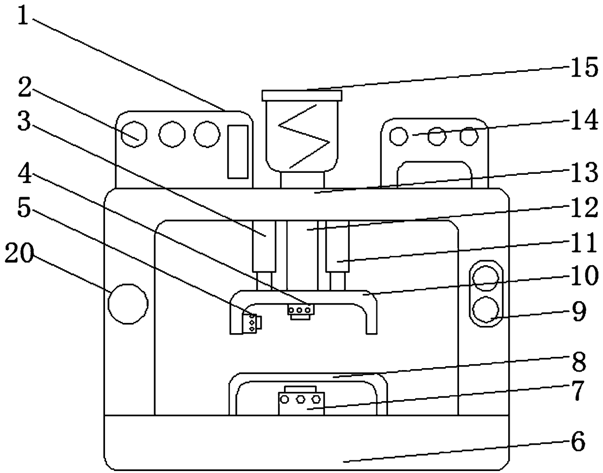
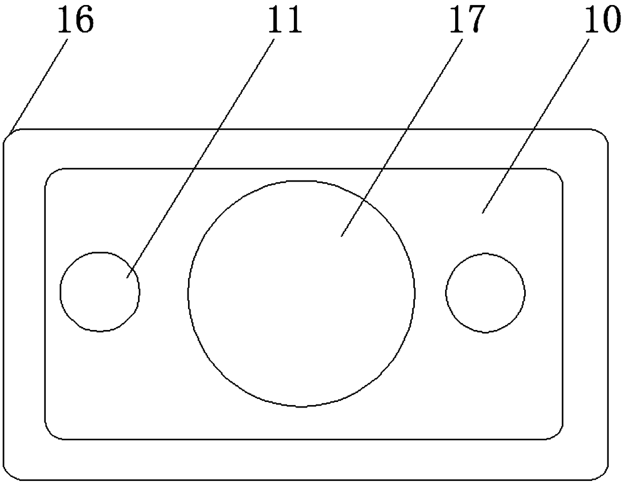
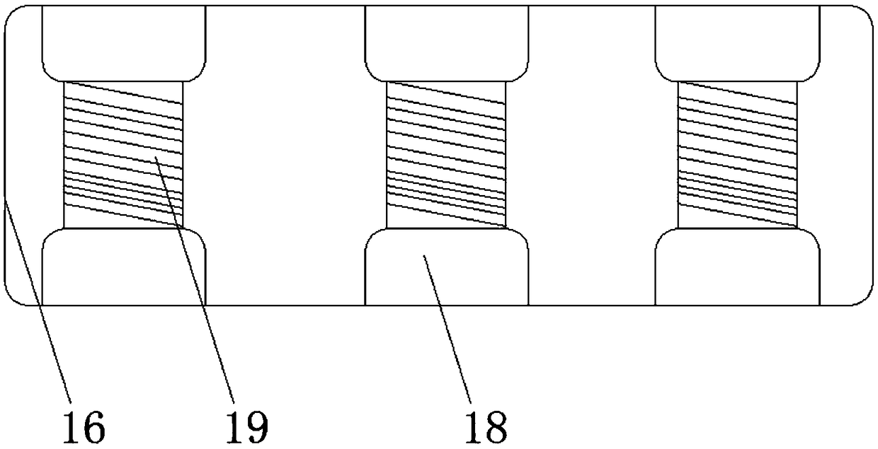
[0015] see Figure 1-3 , an embodiment provided by the present invention: a protective device for a CNC drilling machine, including a power supply box 1, a base 6 and a controller 14, and a fixing frame 13 is installed above the base 6, which can facilitate fixing the whole device It can be moved and used as a whole, which improves the integrity and service efficiency of the device. The surface of the fixed frame 13 is equipped with a warning light 20 through ...


PUM


Abstract

The invention discloses a digital control drilling machine protection device which comprises a power supply box, a base and a controller. A fixing frame is arranged above the base; the power supply box is arranged above the fixing frame; a motor is arranged on the fixing frame on one side of the power supply box; the controller is arranged on the fixing frame on one side of the motor; an output end of the controller is electrically connected with an input end of the motor through a lead wire; input ends of the motor and the controller are electrically connected with an output end of the powersupply box through lead wires; a rotary shaft is arranged at the output end of the motor; a first electric lifting column and a second electric lifting column are arranged on the fixing frame on one side of the rotary shaft; and protection covers are arranged at output ends of the first electric lifting column and the second electric lifting column. Through arranging a series of structure, the device provided by the invention has the advantages of convenience in use, good protection effect, high safety and the like during a drilling machine protection process.

Description

technical field [0001] The invention relates to the technical field of mechanical protection equipment, in particular to a protection device for a numerically controlled drilling machine. Background technique [0002] Drilling machine refers to the general name of machinery and equipment that leaves cylindrical holes or holes on the target by means of rotary cutting or rotary extrusion with a tool that is harder and sharper than the target. Machines, drilling machines, through-hole machines, etc., achieve the desired effect by drilling precision parts. Drilling machines include semi-automatic drilling machines and fully automatic drilling machines. With the increase in human resource costs; most enterprises Both consider fully automatic drilling machines as the development direction. With the development of the times and the improvement of the drilling technology of automatic drilling machines, fully automatic drilling machines are used to drill holes for various metal molds...

Claims


Application Information

Patent Timeline
Patent Type & Authority Applications(China)
IPC IPC(8): B23B47/00B23Q11/00B23Q11/08B23Q11/10B23Q17/24
CPCB23B47/00B23Q11/0032B23Q11/0078B23Q11/08B23Q11/10B23Q17/24
Inventor 王秀兰
Owner 王秀兰
Learn More