
Solar sweeper garbage compression device

A garbage compression and cleaning vehicle technology, which is applied in the field of cleaning vehicles, can solve the problems of reducing the working efficiency of the cleaning vehicle, not having the function of garbage compression, and it is difficult to empty the garbage, so as to reduce the transition time, reduce the volume of garbage, and improve The effect of work efficiency

Pending Publication Date: 2018-10-09
王晓东 +2
View PDF0 Cites 0 Cited by
  • Summary
  • Abstract
  • Description
  • Claims
  • Application Information

AI Technical Summary

Problems solved by technology

[0002] At present, the garbage bins of sweeping vehicles at home and abroad do not have the function of garbage compression. After the garbage enters the garbage box, it presents a natural distribution state. Especially when cleaning light and bulky garbage such as leaves and plastic bags, the garbage box will be full soon. The car needs to transfer garbage to dump, which reduces the working efficiency of the sweeper
No. 2011204164680 patent has introduced the dustbin of the sweeping vehicle. The opening of the small motorized dustbin of the motorized sweeping vehicle in the prior art is usually the bottom opening or the side opening. After the lid is opened, it is tilted. The garbage in the box cannot be emptied at one time. It needs to be turned over many times or assisted by a vibration device. Even so, it is difficult to empty all the garbage in it.
The disadvantages and problems of this method are: when cleaning light and bulky garbage such as leaves and plastic bags, the garbage bin will be full soon, and the sweeper needs to transfer the garbage to dump, which reduces the working efficiency of the sweeper

Method used


Image

  • Solar sweeper garbage compression device
  • Solar sweeper garbage compression device

Examples


Embodiment Construction

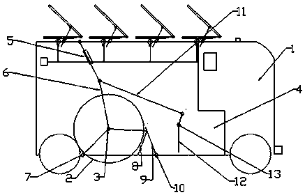
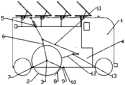
[0009] The working principle and working process of the present invention are as follows: when the solar sweeping vehicle 1 is working, the solar sweeping vehicle 1 moves forward, and the roller brush 2 rotates around the roller brush central axis 3, the direction of rotation is opposite to that of the wheels, and the road garbage is swept into the 4 In the garbage bin, after the garbage bin 4 is full of light and bulky garbage, the electric push rod 5 lifts the roller brush lifting rod 6 upwards, and the roller brush 2 rotates around the roller brush lifting shaft 7 and lifts it upwards, driving the collecting shovel 8 upwards. Movement, lift up the garbage baffle 9 and rotate around the garbage baffle shaft 10 to block the garbage in the garbage bin 4 from spilling, and at the same time, the electric push rod 5 drives the garbage compression plate pull rod 11 to rotate around the garbage compression plate axis 13 to drive garbage compression Plate 12 rotates around the rubbis...


PUM


Abstract

The invention discloses a solar sweeper garbage compression device. The solar sweeper garbage compression device aims to improve the working efficiency of the sweeper. The core part of the solar sweeper garbage compression device is characterized in that when the solar sweeper performs the cleaning work, road garbage is swept into a garbage can, an electric push rod upwards lifts and pulls a rolling brush lifting pull rod, a rolling brush rotates around a rolling brush lifting shaft and is lifted upwards to drive a collecting shovel to move upwards, a garbage baffle is jacked up to rotate around a garbage baffle shaft to be lifted, meanwhile, the electric push rod drives a garbage compression plate pull rod to rotate around a garbage compression plate shaft, and the garbage in the garbagecan is pushed backwards and compressed. In the graph, 1 refers to the solar sweeper, 2 refers to the rolling brush, 3 refers to a rolling brush center shaft, 4 refers to the garbage can, 5 refers to the electric push rod, 6 refers to the rolling brush lifting pull rod, 7 refers to the rolling brush lifting shaft, 8 refers to the collecting shovel, 9 refers to the garbage baffle, 10 refers to the garbage baffle shaft, 11 refers to the garbage compression plate pull rod, 12 refers to the garbage compression plate, and 13 refers to the garbage compression plate shaft.

Description

technical field [0001] The invention relates to a cleaning vehicle, in particular to a garbage compression device for the cleaning vehicle. Background technique [0002] At present, the garbage bins of sweeping vehicles at home and abroad do not have the function of garbage compression. After the garbage enters the garbage box, it presents a natural distribution state. Especially when cleaning light and bulky garbage such as leaves and plastic bags, the garbage box will be full soon. The car needs to transfer to the dump, which reduces the working efficiency of the sweeper. No. 2011204164680 patent has introduced the dustbin of the sweeping vehicle. The opening of the small motorized dustbin of the motorized sweeping vehicle in the prior art is usually the bottom opening or the side opening. After the cover body is opened, it is inclined, and the garbage in the box cannot be poured out at one time. It needs to be turned over many times or assisted by a vibrating device. Eve...

Claims


Application Information

Patent Timeline
IPC IPC(8): B65F3/14E01H1/04
CPCB65F3/14E01H1/047Y02W30/10
Inventor 王晓东刘智英史素娟
Owner 王晓东
Learn More