
Transfer device

A material transfer vehicle and driving device technology, applied in storage devices, transportation and packaging, etc., can solve the problems of inconvenient installation, low efficiency, time-consuming and labor-intensive, etc., and achieve the effect of simple structure, reasonable design and convenient installation.

Pending Publication Date: 2018-10-09
NANTONG MUYE MACHINERY
View PDF0 Cites 0 Cited by
  • Summary
  • Abstract
  • Description
  • Claims
  • Application Information

AI Technical Summary

Problems solved by technology

[0002] During sponge processing, the strip-shaped sponge blocks that have been cut are usually manually transferred to the storage wire rack for storage, which is time-consuming, laborious, and inefficient; The material platforms are arranged in sequence, and the overall length of the material transfer device is too long, which is not convenient for general factory installation

Method used


Image

  • Transfer device
  • Transfer device
  • Transfer device

Examples


specific Embodiment 1

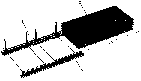
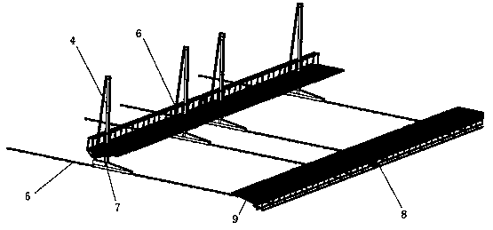
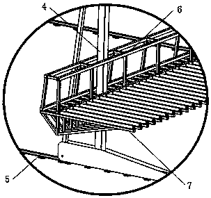
[0023] Such as Figure 1-4 , a kind of material transfer device, the material transfer device is cooperatingly arranged on one side of the storage wire frame, and it includes a material transfer car 1 and a foaming machine material transfer platform 2 arranged opposite to each other; the material transfer car 1 includes several vertically arranged vertical frame 4, several guide rails 5 arranged in parallel horizontally, and vertical slides 6, the vertical frame 4 corresponds to the guide rails 5 one by one, the vertical frame 4 is slidably installed on the guide rail, and moves along the direction of the guide rail, and the vertical slide frame 6 is slidably installed on the On the vertical frame, several vertical frames 4 jointly support the vertical slide frame 6, and the vertical slide frame 6 moves along the vertical direction on the vertical frame 4, and a plurality of first support horizontal frames 7 are horizontally and vertically arranged on one side of the vertical s...

specific Embodiment 2

[0024] Such as Figure 1-4 , on the basis of the specific embodiment 1, a sprocket is further set on the end of the roller on the first support horizontal frame 7 near the side of the vertical carriage 6, and the end of the roller on the second support horizontal frame 9 is fitted on the side close to the support platform 8 There is a sprocket, the sprocket and the main sprocket are connected by a chain, the main sprocket is set on the output shaft of the roller motor, and the roller motor is respectively installed on the platform bracket and the vertical carriage, and the electric control box is connected to the first driving device, the second The second driving device, the drum motor, the motor of the storage wire rack and the detection sensor, the detection sensor is respectively arranged at various parts of the material transfer vehicle, so as to facilitate the automatic operation of the material transfer device.

specific Embodiment 3

[0025] Such as Figure 1-4 , on the basis of the specific embodiment 1 or 2, the further described first driving device adopts a cylinder or a hydraulic cylinder or a motor to cooperate with rollers and guide rails; the second driving device adopts a servo motor and a sprocket chain arranged in cooperation with the servo motor Or rack and pinion form.


PUM


Abstract

The invention relates to a transfer device which is arranged on one side of a wire storage rack in a matched mode. The transfer device comprises a transfer trolley and a foaming machine transfer platform which are arranged oppositely in a separated mode. A plurality of first supporting transverse frames are evenly arranged on the transfer trolley. A plurality of second supporting transverse framesare evenly arranged on the foaming machine transfer platform. The second supporting transverse frames and the first supporting transverse frames are arranged oppositely in a mutually staggered mode.The transfer device is reasonable in design and simple in structure and achieves mechanical transferring of sponge blocks, convenience and rapidness are achieved, and time and labor are both saved; and by means of the transfer trolley and the foaming machine transfer platform which are arranged side by side, the overall length of the transfer device is reduced by half compared with an original transfer device, and thus the transfer device can be conveniently installed in ordinary plants.

Description

technical field [0001] The invention relates to the field of sponge processing, in particular to a material transfer device. Background technique [0002] During sponge processing, the strip-shaped sponge blocks that have been cut are usually manually transferred to the storage wire rack for storage, which is time-consuming, laborious, and inefficient; The material platforms are arranged in sequence, and the overall length of the material transfer device is too long, which is not convenient for general factory installation. Contents of the invention [0003] In order to solve the above problems, the present invention proposes a material transfer device, which is reasonable in design and simple in structure, and realizes the mechanical transfer of sponge blocks, which is convenient, fast, time-saving and labor-saving, and uses a material transfer car and a foaming machine arranged side by side to transfer materials The platform shortens the overall length of the device by ...

Claims


Application Information

Patent Timeline
IPC IPC(8): B65G1/04
CPCB65G1/0428
Inventor 缪小龙
Owner NANTONG MUYE MACHINERY
Learn More