Novel flow guide groove structure for cabinet inner machine

A technology of diversion tanks and cabinet units, which can be used in household heating, condensation prevention, lighting and heating equipment, etc., and can solve problems such as short circuits

Pending Publication Date: 2018-10-09
GREE ELECTRIC APPLIANCES INC
View PDF6 Cites 2 Cited by
  • Summary
  • Abstract
  • Description
  • Claims
  • Application Information

AI Technical Summary

Problems solved by technology

However, during the cooling process, a layer of condensed water will be formed on the outer surface of the frame. When the condensed water accumulates to a certain extent, it will flow under the frame, and the lower end of the frame is equipped with moving parts, and the moving parts are equipped with motors, micro Electrical components such as dynamic switches can easily lead to faults such as short circuits. Therefore, it is necessary to develop a new diversion groove structure to guide the condensed water over the moving parts into the water receiving tray on the base.

Method used


Image

  • Novel flow guide groove structure for cabinet inner machine
  • Novel flow guide groove structure for cabinet inner machine
  • Novel flow guide groove structure for cabinet inner machine

Examples


Embodiment Construction

[0020] The technical solution of the present invention will be described in further detail below through specific examples, but it must be pointed out that the following examples are only used to describe the content of the invention, and do not constitute limitations to the protection scope of the present invention.

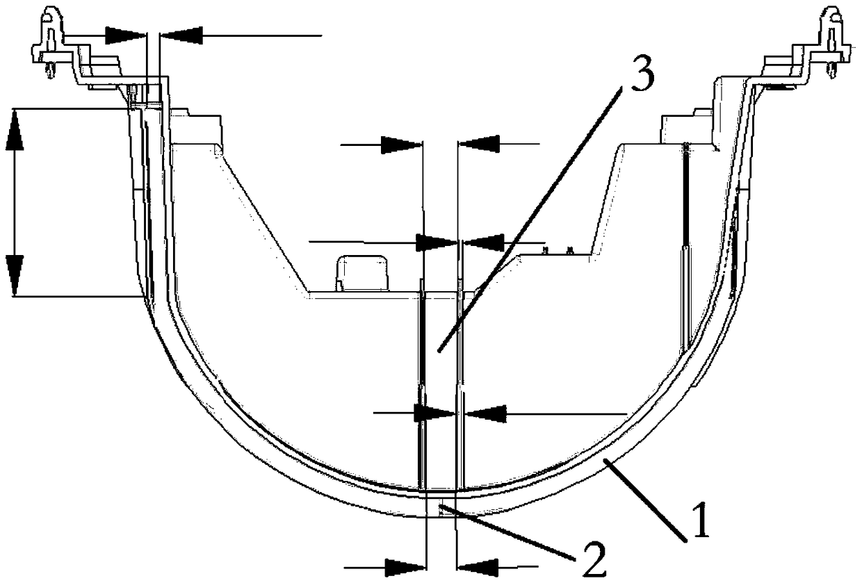
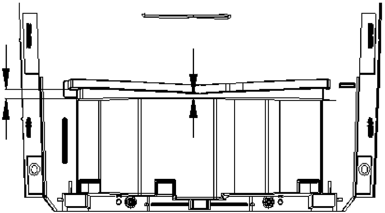
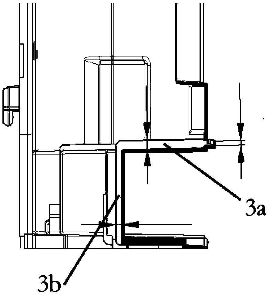
[0021] The lower moving part of the cabinet unit is located at the lower end of the water receiving tank 1 of the support plate (skeleton), and the outside of the water receiving tank 1 is the air outlet panel part. The outer edge of the air outlet panel and the water receiving tank 1 must have a gap of more than 5 mm, and that is, the upper edge of the water receiving tank 1 needs to keep a distance of more than 10 mm from the grille on the air outlet panel part. The space here is extremely small, and the structure of the docking sink 1 has many restrictions, so the traditional method of adding water bowls to divert water cannot be used. Therefore, according to ...


PUM


Abstract

The invention discloses a novel flow guide groove structure for a cabinet inner machine. The flow guide groove structure comprises a water receiving groove, a flow guide hole, a flow guide groove andribs. The water receiving groove is formed in the outer side of a skeleton of the cabinet inner machine in a surrounding manner. The two ends of the water receiving groove incline inwards. The water receiving groove comprises a bottom connected with the skeleton and a side portion connected with the bottom. The side portion is bent outwards relative to the bottom. The flow guide hole is formed inthe front face of the skeleton of the cabinet inner machine and located in the center of the water receiving groove. The flow guide groove is formed in the inner side of the skeleton of the cabinet inner machine. The flow guide groove is located right behind the flow guide hole to enable the front portion and the rear portion of the skeleton to communicate. The two sides of the flow guide groove are provided with the ribs. The flow guide groove is arranged to be of a structure shaped like the inverted arable number seven. A lower moving part is arranged in a cavity of the flow guide groove toachieve the waterproof effect. The flow guide groove comprises a horizontal section and a vertical section. The horizontal section is located on the rear portion of the water receiving groove and located above the lower moving part of the cabinet inner machine. The vertical section is located on the back of the lower moving part of the cabinet inner machine, a water receiving disc on a chassis isconnected under the vertical section, and condensation water passes over the moving part and flows in the water receiving disc on the base.

Description

technical field [0001] The invention belongs to the technical field of air conditioners, and relates to a diversion structure, in particular to a novel diversion groove structure of an in-cabinet unit. Background technique [0002] As the main model of the air conditioner, the cylindrical cabinet machine adopts a new one-piece skeleton structure and the functions of left and right sweeping and front pushing; in order to meet the design and appearance requirements, it adopts a structure in which the upper and lower moving parts are arranged separately . However, during the cooling process, a layer of condensed water will be formed on the outer surface of the frame. When the condensed water accumulates to a certain extent, it will flow under the frame, and the lower end of the frame is equipped with moving parts, and the moving parts are equipped with motors, micro Therefore, it is necessary to develop a new diversion groove structure to divert the condensed water over the mo...

Claims


Application Information

Patent Timeline
Patent Type & Authority Applications(China)
IPC IPC(8): F24F13/22
CPCF24F13/222
Inventor 程昆鹏陈珠秀陈瑶黎民驱马雄李德清潘龙腾余明养
Owner GREE ELECTRIC APPLIANCES INC
Why Eureka
Try Eureka