
Special roller for anti-static treadmill

A treadmill, anti-static technology, applied in the direction of static electricity, electrical components, sports accessories, etc., can solve the problems of static suppression and anti-static effect, poor operation of electronic components of treadmill, health hazards of users, etc.

Pending Publication Date: 2021-04-09
晋江市名禾机械配件有限公司
View PDF6 Cites 0 Cited by
  • Summary
  • Abstract
  • Description
  • Claims
  • Application Information

AI Technical Summary

Problems solved by technology

[0003] The operating principle of the current treadmill mainly relies on the motor to drive the drum to move through transmission devices such as belts, so that the running belt that is sleeved on the drum is constantly moving. At this time, the user can run on the running belt; Continuous operation and constant friction between the sole and the running belt will generate static electricity on the treadmill. If the static electricity is not properly handled, it will cause harm to a series of electronic components such as the motor and controller in the treadmill. In addition, a large amount of accumulated The static electricity will also cause harm to the health of users, so how to suppress and eliminate static electricity is a problem that manufacturers cannot ignore
[0004] At present, the industry mainly adopts the static electricity guide method, that is, the ground wire is connected to the treadmill frame, but the effect of suppressing and eliminating static electricity is not ideal, and the static electricity will still gradually accumulate, making the treadmill prone to poor operation of electronic components , the roller is in direct contact with the belt and the running belt. If a roller that can suppress and eliminate static electricity is developed, it will be of positive significance to solve the above problems and promote the development of the industry.

Method used


Image

  • Special roller for anti-static treadmill
  • Special roller for anti-static treadmill

Examples


Embodiment

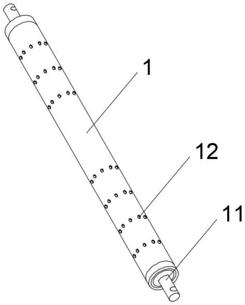
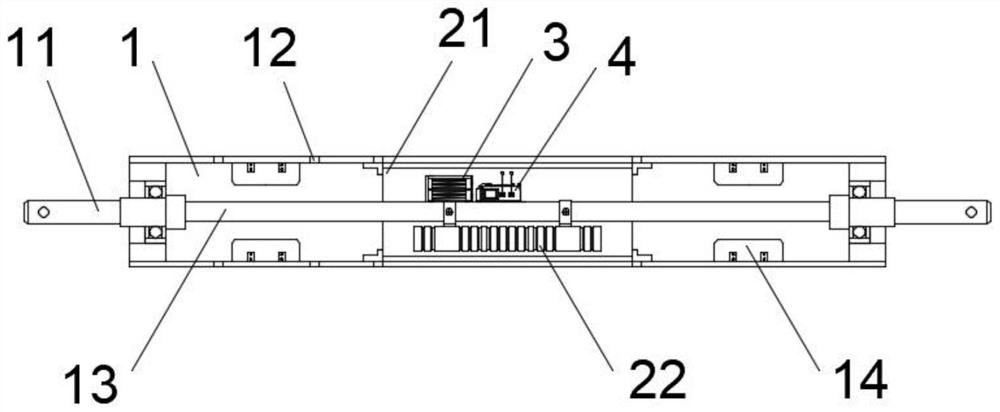
[0022] combine Figure 1-2 , a special roller for an anti-static treadmill, including a roller body 1, a power generating device, a voltage transforming device 3 and a static elimination device 4, the two ends of the roller body 1 are rotatably provided with installation shafts 11, and the two ends of the roller body 1 The end is provided with a bearing, the installation shaft 11 is rotatable through the bearing, the surface of the drum body 1 is provided with ventilation holes 12, and several blades 14 are integrally arranged in the drum body 1, and the blades 14 are respectively arranged On both sides of the drum body 1, the drum body 1 is provided with a connecting shaft 13, both ends of the connecting shaft 13 are connected with the installation shaft 11, and the installation shaft 11 and the connection shaft 13 are integrated structure, the power generation device is arranged in the drum body 1, the power generation device includes a rotor 21 and a stator 22, the rotor 21...


PUM


Abstract

The invention relates to the technical field of treadmills and particularly relates to a special roller for an anti-static treadmill. The special roller comprises a roller body, a power generation device, a voltage transformation device and a static elimination device, and utilizes continuous rotation of the roller to generate induced electromotive force when the treadmill is started to excite the static elimination device after voltage transformation of the voltage transformation device. The static electricity eliminating device ionizes air in the roller body to enable the air to be rich in positive and negative ions, the air containing a large number of positive and negative ions can neutralize static electricity existing in a belt, a running belt and other components after being exhausted through the ventilation holes, wiring of the treadmill cannot be affected, and the air rich in positive and negative ions can permeate to all positions of the treadmill; practical significance and popularization value are achieved, and it is expected that good economic benefits can be generated.

Description

technical field [0001] The invention relates to the technical field of treadmills, in particular to a special roller for antistatic treadmills. Background technique [0002] Treadmill is a common fitness equipment for families and gyms, and it is the simplest type of home fitness equipment today. It is the best choice for home fitness equipment. At present, with the development of science and technology, the functions of treadmills are becoming more and more abundant, which improves the comfort of users and gradually enters thousands of households. [0003] The operating principle of the current treadmill mainly relies on the motor to drive the drum to move through transmission devices such as belts, so that the running belt that is sleeved on the drum is constantly moving. At this time, the user can run on the running belt; Continuous operation and constant friction between the sole and the running belt will generate static electricity on the treadmill. If the static elect...

Claims


Application Information

Patent Timeline
IPC IPC(8): A63B22/02H05F3/04
CPCA63B22/0235H05F3/04
Inventor 李春华
Owner 晋江市名禾机械配件有限公司
Learn More