
Two-stage compression refrigeration system with expansion and pressurization

A refrigeration system and two-stage compression technology, which is applied to irreversible cycle compressors, compressors, refrigerators, etc., can solve the problems of low performance coefficient of single-stage compression refrigeration cycle, complex structure of refrigeration system, and high degree of wear of compressors. , to achieve the effect of simple structure, high system energy efficiency ratio and improved energy efficiency ratio

Pending Publication Date: 2018-10-09
天津市正源制冷设备有限公司
View PDF0 Cites 0 Cited by
  • Summary
  • Abstract
  • Description
  • Claims
  • Application Information

AI Technical Summary

Problems solved by technology

This temperature requirement has the following disadvantages for the application of single-stage compression refrigeration cycle: the compressor works for a long time between a large working pressure difference, which consumes a lot of power and wears the compressor greatly, resulting in the performance of the single-stage compression refrigeration cycle. The coefficient is relatively low and the maintenance cost is high
This temperature requirement has the following disadvantages for the two-stage compression refrigeration cycle: the structure of the refrigeration system is complex and the input cost is high, so it is very necessary to optimize the two-stage compression refrigeration cycle system
Both the single-stage compression refrigeration system and the two-stage compression refrigeration system have the following disadvantages: the throttling process of the throttling and step-down element has a large loss, resulting in a large increase in the entropy of the entire refrigeration cycle and a low performance coefficient of the system.

Method used


Image

  • Two-stage compression refrigeration system with expansion and pressurization

Examples


Embodiment Construction

[0020] The present invention will be further described below in conjunction with specific embodiments.

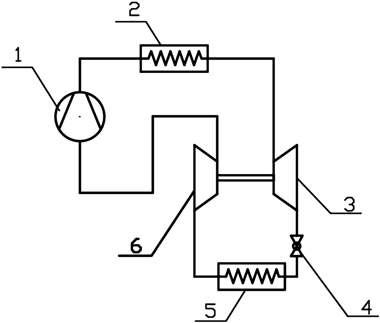
[0021] The principle diagram of a two-stage compression refrigeration system with expansion and boosting of the present invention is as follows figure 1 As shown, a functional compressor 1, a condenser 2, an expander 3, a throttling element 4, an evaporator 5, and a booster compressor 6 are included. The exhaust port of the functional compressor 1 is connected to the inlet of the condenser 2, the outlet of the condenser 2 is connected to the inlet end of the expander 3, and the outlet end of the expander 3 is connected to the joint The inlet end of the flow element 4 is connected, the outlet end of the throttle element 4 is connected with the inlet of the evaporator 5, the outlet of the evaporator 5 is connected with the suction port of the booster compressor 6, and the The discharge port of the booster compressor 6 is connected to the suction port of the functional compresso...


PUM


Abstract

The invention discloses a two-stage compression refrigeration system with expansion and pressurization, and aims to provide a system capable of reducing the loss in the throttling process and improving the system energy efficiency. An exhaust port of a functional compressor is connected with an inlet of a condenser, and an outlet of the condenser is connected with the inlet end of an expansion machine; the outlet end of the expansion machine is connected with the inlet end of a throttling element; the outlet end of the throttling element is connected with an inlet of an evaporator, and an outlet of the evaporator is connected with a gas sucking port of a pressurization compressor; and an exhaust port of the pressurization compressor is connected with a gas sucking port of the functional compressor, and the expansion machine drives the pressurization compressor. According to the refrigeration system, the expansion machine expands to do work so as to drive the pressurization compressor to run, the pressurization compressor sucks in low-pressure steam work media and compresses the low-pressure steam work media to be in medium pressure, the first-stage compression is completed, the loss in the throttling process is reduced, the entropy increase of the refrigeration cycle is reduced, and the energy efficiency ratio of the circulation system is increased. Besides, the structure is simple, and cost is low.

Description

Technical field [0001] The present invention relates to the technical field of refrigeration, and more specifically, to a two-stage compression refrigeration system with expansion and boost. Background technique [0002] When lower temperature refrigeration is required, single-stage compression or two-stage compression refrigeration cycles are usually used. This temperature requirement has the following shortcomings for the application of single-stage compression refrigeration cycle: the compressor works for a long time between a large working pressure difference, which consumes a lot of power and wears a lot of the compressor, resulting in the performance of the single-stage compression refrigeration cycle The coefficient is relatively low and the maintenance cost is high. This kind of temperature demand has the following shortcomings for the two-stage compression refrigeration cycle: the refrigeration system has a complex structure and high investment costs, so it is very nece...

Claims


Application Information

Patent Timeline
IPC IPC(8): F25B1/10F25B31/00
CPCF25B1/10F25B31/00
Inventor 罗永生
Owner 天津市正源制冷设备有限公司
Learn More