Magnetic resonance spectrometer and magnetic resonance imaging system

A magnetic resonance spectrometer and coil technology, applied in the direction of instruments, measuring magnetic variables, measuring devices, etc., can solve the problems of inconvenient portability, expensive network analyzers, and easy damage during long-term transportation

Active Publication Date: 2018-10-09
SHANGHAI NEUSOFT MEDICAL TECH LTD
View PDF4 Cites 5 Cited by
  • Summary
  • Abstract
  • Description
  • Claims
  • Application Information

AI Technical Summary

Problems solved by technology

[0004] At present, network analyzers are generally used to measure the performance indicators of RF coils, but network analyzers are expensive, inconvenient to carry, and easily damaged during long-term transportation

Method used


Image

  • Magnetic resonance spectrometer and magnetic resonance imaging system
  • Magnetic resonance spectrometer and magnetic resonance imaging system
  • Magnetic resonance spectrometer and magnetic resonance imaging system

Examples


Embodiment 1

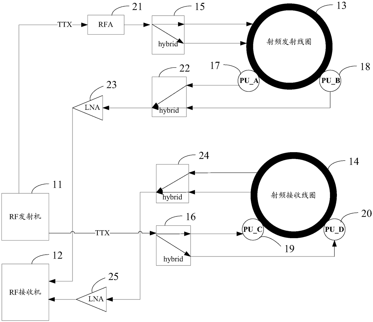
[0051] see figure 1 , figure 2 , The magnetic resonance spectrometer provided by Embodiment 1 of the present application includes: a radio frequency transmitter 11 (RF transmitter), a radio frequency receiver 12 (RF receiver), a radio frequency transmitting coil 13, a radio frequency receiving coil 14, and also includes: a first Power splitter (hybrid) 15, the second power splitter 16, the first pick-up coil 17 (PU_A) and the second pick-up coil 18 (PU_B) that are arranged on both sides of the radio frequency transmitting coil 13, and the two sides that are arranged on the radio frequency receiving coil 14 The third pickup coil 19 (PU_C) and the fourth pickup coil 20 (PU_D) on the side.

[0052] Wherein, the first power divider 15 is connected with the radio frequency transmitter 11 and the radio frequency transmitting coil 13; The first power divider 14 is used to divide the test signal (TTX) transmitted by the radio frequency transmitter 11 into an I signal and a Q signal,...

Embodiment 2

[0077] The magnetic resonance spectrometer provided in the second embodiment of the present application is similar to the magnetic resonance spectrometer provided in the first embodiment of the present application, and the same parts will not be repeated here, and only the different parts will be described below.

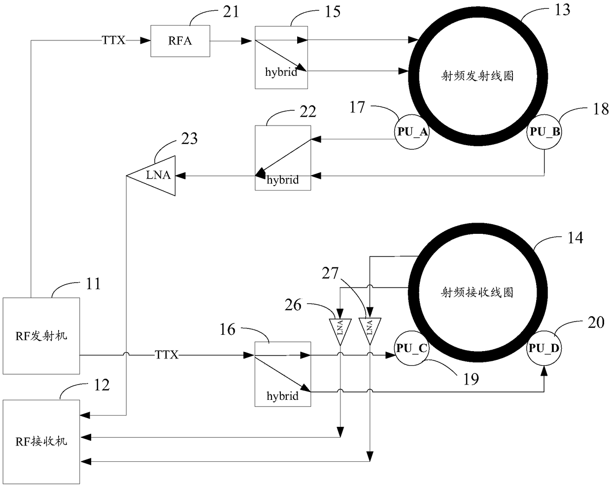
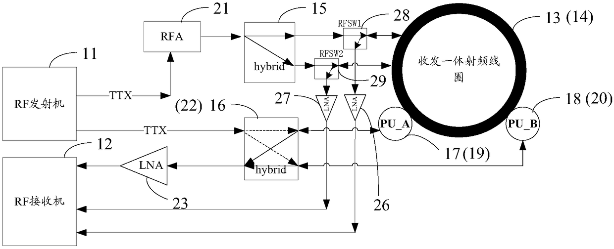
[0078] see image 3 , Figure 4 In the magnetic resonance spectrometer provided in Embodiment 2 of the present application, the radio frequency transmitting coil 13 and the radio frequency receiving coil 14 are integrally arranged, that is to say, the radio frequency coil in the magnetic resonance spectrometer is an integrated radio frequency coil for transmitting and receiving, such as an orthogonal body coil (QBC coil).

[0079] In a possible implementation, such as image 3 , Figure 4 As shown, the first pickup coil 17 and the third pickup coil 19 can be arranged integrally, and the second pickup coil 18 and the fourth pickup coil 20 can be arranged integrall...


PUM


Abstract

The invention provides a magnetic resonance spectrometer and a magnetic resonance imaging system, so as to realize the performance index of radio frequency coil self-detecting of the magnetic resonance imaging system. The magnetic resonance spectrometer comprises a radio frequency transmitter, a radio frequency receiver, a radio frequency transmitting coil and a radio frequency receiving coil. Themagnetic resonance spectrometer is characterized in that the magnetic resonance spectrometer further comprises a first power splitter, a second power splitter, first and second pick-up coils which are arranged on both sides of the radio frequency transmitting coil, and third and fourth pick-up coils which are arranged on both sides of the radio frequency receiving coil; the first power splitter is connected with the radio frequency transmitter and the radio frequency transmitting coil; the second power splitter is connected with the radio frequency transmitter, the third pick-up coil and thefourth pick-up coil; the first pick-up coil and the second pick-up coil are connected with the radio frequency receiver; and the radio frequency receiving coil is connected with the radio frequency receiver.

Description

technical field [0001] The present application relates to the field of magnetic resonance technology, in particular to a magnetic resonance spectrometer and a magnetic resonance imaging system. Background technique [0002] MRI (Magnetic Resonance Imaging, MRI) system is a modern medical imaging device that generates resonance phenomena through radio frequency field excitation, and realizes visual imaging of human tissue and structure. [0003] The radio frequency coils in the magnetic resonance imaging system (for example: radio frequency transmitting coils, radio frequency receiving coils, and radio frequency coils integrated with transceivers) are key components that affect image quality. (FOV) required bandwidth, so measuring the performance index of the RF coil is a very complicated and important task, and it is necessary to regularly check the passband bandwidth, resonance frequency, and in-band flatness of the RF coil. [0004] At present, network analyzers are gener...

Claims


Application Information

Patent Timeline
Patent Type & Authority Applications(China)
IPC IPC(8): G01R35/00G01R33/58
CPCG01R33/58G01R35/00
Inventor 王宏伟李海泉史建华王艳
Owner SHANGHAI NEUSOFT MEDICAL TECH LTD
Why Eureka
Try Eureka