A wireless charging circuit and system

A wireless charging and charging circuit technology, which is applied in the direction of battery circuit devices, circuit devices, collectors, etc., can solve the problems of reduction and change in the energy and power transmission capacity of the charging system, and achieve high charging efficiency, high output power capability, Avoid mutual interference effects

Active Publication Date: 2019-09-03
SHENZHEN DONGZHOU NEW ENERGY TECH
View PDF3 Cites 0 Cited by
  • Summary
  • Abstract
  • Description
  • Claims
  • Application Information

AI Technical Summary

Problems solved by technology

However, according to the distance between the electromagnetic induction coils, the coupling state of the wireless charging system will also change; if the distance is smaller, the coupling degree will also increase. At this time, the transmission and reception frequency of wireless energy is accelerated, and the power transmission capacity of the charging system The efficiency and efficiency will increase at the same time, but when the coupling coefficient increases to a certain value, the receiving circuit of the subsequent stage will generate a reflected voltage to the transmitting circuit of the previous stage, so that the energy and power transmission capacity of the charging system will also decrease with the further reduction of the distance. Small

Method used


Image

  • A wireless charging circuit and system
  • A wireless charging circuit and system
  • A wireless charging circuit and system

Examples


Embodiment Construction

[0029] The following will clearly and completely describe the technical solutions in the embodiments of the present invention with reference to the accompanying drawings in the embodiments of the present invention. Obviously, the described embodiments are only some, not all, embodiments of the present invention. Based on the embodiments of the present invention, all other embodiments obtained by persons of ordinary skill in the art without creative efforts fall within the protection scope of the present invention.

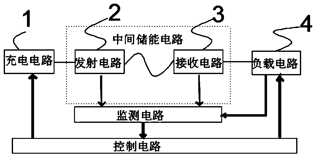
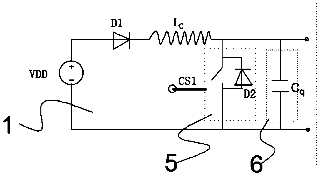
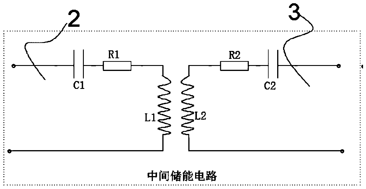
[0030] see figure 1 , providing a circuit schematic diagram of a wireless charging circuit; in this embodiment, a wireless charging circuit is provided, including a charging circuit 1, an intermediate energy storage circuit, a load circuit 4, and a control circuit; the intermediate energy storage circuit includes The transmitting circuit 2 and the receiving circuit 3; the charging circuit is used to store the electric energy of the external power supply into the ch...


PUM


Abstract

The invention provides a wireless charging circuit which comprises a charging circuit, an intermediate energy storage circuit, a load circuit and a control circuit; wherein the intermediate energy storage circuit comprises a transmitting circuit and a receiving circuit; the input end of the charging circuit is connected with an external direct-current power supply, and the output end of the charging circuit is connected to the input end of the transmitting circuit in an electric connection mode; the output end of the transmitting circuit is connected to the input end of the receiving circuit in a magnetic induction coupling mode; the output end of the receiving circuit is connected to the input end of the load circuit; and the transmitting circuit and the receiving circuit are both a resonance circuit. By means of resonance, the energy of the transmitting circuit is wirelessly transmitted to the input end of the receiving circuit through the output end of the transmitting circuit. Theoutput end of the load circuit is connected with a load; the control circuit is used for controlling the charging circuit, the transmitting circuit and the receiving circuit, the working time sequenceof the load circuit under different working states is controlled. According to the wireless charging circuit, the charging efficiency is high, and the higher output power capability is also ensured.

Description

technical field [0001] The invention relates to the technical field of wireless charging, in particular to a wireless charging circuit and system. Background technique [0002] Wireless power transmission technology, in the 1890s, Nikola Tesla invented the "Tesla coil", which was able to transmit power through the air, and since then opened the era of wireless power transmission. [0003] Wireless charging technology is a relatively popular charging technology at present. Because the charger and the power-consuming device transmit energy through a magnetic field, the two do not need to be connected by wires, so the charger and the power-consuming device can be made without exposed conductive contacts. It has the characteristics of convenient use, beautiful appearance and brief introduction, and is widely used in electronic products such as mobile smart terminals. [0004] In the traditional wireless charging scheme, the receiving end realizes the transmission of energy thro...

Claims


Application Information

Patent Timeline
Patent Type & Authority Patents(China)
IPC IPC(8): H02J7/00H02J50/12
CPCH02J7/00H02J7/025H02J50/12
Inventor 蒋笑邢普润
Owner SHENZHEN DONGZHOU NEW ENERGY TECH
Why Eureka
Try Eureka