Eureka AIR delivers breakthrough ideas for toughest innovation challenges, trusted by R&D personnel around the world.

Vehicle-mounted electromagnetic oscillation signal receiving device

A signal receiving device and electromagnetic oscillation technology, applied in electrical components, transmission systems and other directions, can solve the problems of poor signal reception effect of communication and entertainment equipment, unable to meet the daily needs of car owners, inconvenient in and out of parking lots and garages, etc. The body flow line is more dynamic, the body flow line is beautiful and beautiful, and the installation is convenient, simple and fast.

Active Publication Date: 2018-10-09
赵东方
View PDF7 Cites 0 Cited by
  • Summary
  • Abstract
  • Description
  • Claims
  • Application Information

AI Technical Summary

Problems solved by technology

[0002] With the progress of society and the improvement of living standards, cars are becoming more and more popular, and there are more and more communication and entertainment devices (radio, telephone, Bluetooth, navigation, WIFI, TV, etc.) in the car. For equipment signal reception, most of the car roofs are equipped with one or more long pigtail antenna poles to receive the required signals, which not only affects the appearance, but also is extremely inconvenient to enter and exit the parking lot and garage. It's extremely cumbersome to screw it down and screw it on again.
[0003] Later, some people used springs and iron rods to shrink or put a small piece of wire-wound PCB board into the fish-fin plastic shell to replace the long pigtail antenna rod, but this can only solve the problem of entering and exiting the parking garage and car washing. , on the contrary, the signal reception effect of communication and entertainment equipment is extremely poor, which cannot meet the daily needs of car owners.

Method used


Image

  • Vehicle-mounted electromagnetic oscillation signal receiving device
  • Vehicle-mounted electromagnetic oscillation signal receiving device
  • Vehicle-mounted electromagnetic oscillation signal receiving device

Examples


Embodiment Construction

[0022] The present invention will be further described below in conjunction with the accompanying drawings.

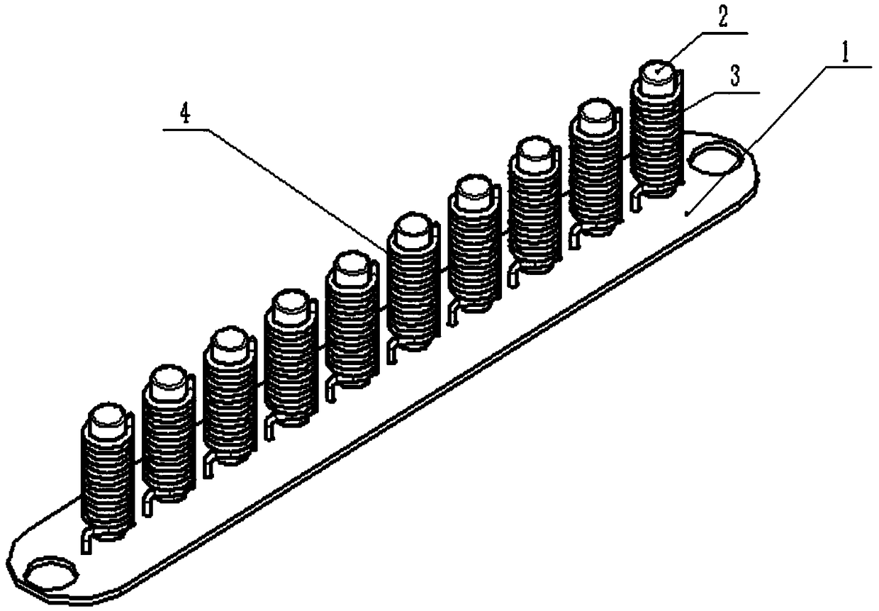
[0023] like figure 1 as shown, figure 1 It is a schematic diagram of the finished vehicle electromagnetic oscillation signal receiving device. 1-10 in the figure is a magnetic rod core inductor 4 made of an electromagnetic core 1 and a metal wire 2. An electromagnetic oscillator is composed of a plurality of magnetic rod core inductors 4 to receive different signals. The frequency signal is then transmitted from terminal A or terminal B of the substrate to the in-vehicle communication and entertainment equipment through the signal transmission line. figure 1 In 1-10, the magnetic rod core inductance 4 forms an electromagnetic oscillator in series or parallel through the substrate 1. In use, the signals required by different communication and entertainment equipment and the signals received by different magnetic rod core inductances are automatically adapted. The freq...


PUM


Abstract

The invention discloses a vehicle-mounted electromagnetic oscillation signal receiving device. The device comprises magnetic rod core inductors and a substrate arranged at the bottom portion. The leftand right two ends of the substrate are signal output ports respectively. Frequency signals mainly received by the different magnetic rod core inductors in the device are different; and the receivedfrequency signals are input to vehicle-mounted communication and entertainment equipment from the signal output ports of the substrate through signal transmission lines. The device reduces use of antennas; and by designing reception of the different vehicle-mounted communication and entertainment equipment signals in one electromagnetic oscillation signal receiving device, and using the magnetic rod core inductors to receive the signals, the device is not only beautiful but also very practical.

Description

technical field [0001] The invention relates to the field of vehicle signal receiving, in particular to a vehicle electromagnetic oscillation signal receiving device. Background technique [0002] With the progress of society and the improvement of living standards, cars are becoming more and more popular, and there are more and more communication and entertainment devices (radio, telephone, Bluetooth, navigation, WIFI, TV, etc.) in the car. For equipment signal reception, most of the car roofs are equipped with one or more long pigtail antenna poles to receive the required signals, which not only affects the appearance, but also is extremely inconvenient to enter and exit the parking lot and garage. It's extremely cumbersome to screw it down and screw it back on. [0003] Later, some people used springs and iron rods to shrink or put a small piece of wire-wound PCB board into the fish-fin plastic shell to replace the long pigtail antenna rod, but this can only solve the pr...

Claims


Application Information

Patent Timeline
Patent Type & Authority Applications(China)
IPC IPC(8): H04B1/08H04B1/00
CPCH04B1/0064H04B1/082
Inventor 赵东方
Owner 赵东方
Why Eureka
Eureka Blog
Learn More