Method and device for multi-antenna transmission in base station and user equipment
A multi-antenna transmission and user equipment technology, applied in the field of multi-antenna transmission, can solve the problem of low reliability and achieve the effect of saving the cost of beam information reporting
- Summary
- Abstract
- Description
- Claims
- Application Information
AI Technical Summary
Problems solved by technology
Method used
Image
Examples
Embodiment 1
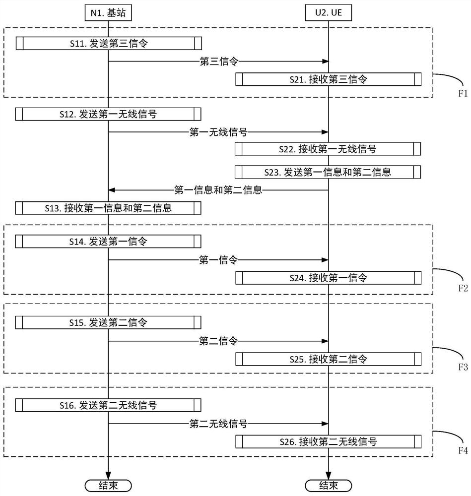
[0182] Embodiment 1 illustrates the flow chart of wireless transmission, as attached figure 1 shown. in the attached figure 1 In , the base station N1 is the serving cell maintenance base station of the UE U2. attached figure 1 , the steps in Box F1, Box F2, Box F3 and Box F4 are optional.
[0183] For N1, send the third signaling in step S11; send the first wireless signal in step S12; receive the first information and the second information in step S13; send the first order in step S14; send in step S15 Second signaling: sending a second wireless signal in step S16.
[0184] For U2, the third signaling is received in step S21; the first wireless signal is received in step S22; the first information and the second information are received in step S23; the first signaling is received in step S24; Receiving second signaling; receiving a second wireless signal in step S26.
[0185] In Embodiment 1, K antenna port groups are used by N1 to send the first wireless signal. Th...
Embodiment 2
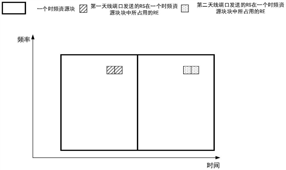
[0194] Embodiment 2 exemplifies the RS (Reference Signal, reference signal) transmitted by one antenna port in one radio resource block, as shown in the attached figure 2 shown. attached figure 2 , the box marked by the thick line is a time-frequency resource block, and the small square filled with oblique lines is the RE (Resource Elements, resource particle) occupied by the RS sent by the first antenna port in a time-frequency resource block. The small squares filled with dots are the REs occupied by the RS sent by the second antenna port in one time-frequency resource block. The first antenna port and the second antenna port are two different antenna ports in this application.
[0195] As a sub-embodiment 1 of Embodiment 2, the time-frequency resource block includes 12 subcarriers in the frequency domain.
[0196] As a sub-embodiment 2 of Embodiment 2, the time-frequency resource block includes 14 OFDM (Othogonal Frequency Division Multiplexing, Orthogonal Frequency Di...
Embodiment 3
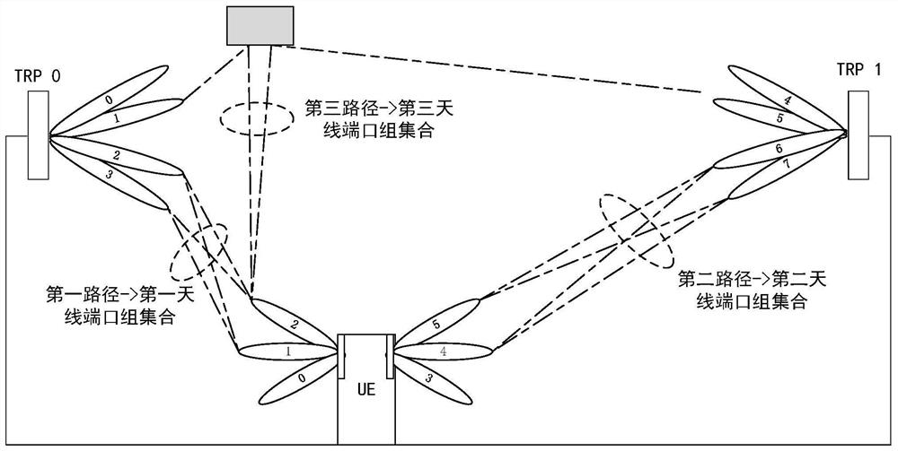
[0200] Embodiment 3 exemplifies K antenna port groups and L antenna port group sets, as shown in the attached image 3 shown. in the attached image 3 In , the gray filled rectangles are reflectors.
[0201] In Embodiment 3, K antenna port groups are 48 antenna port groups, and L antenna port group sets are 3 antenna port group sets. Two TRPs are used to send reference signals, each TRP uses 4 transmit beams to send reference signals, the UE uses two antenna panels with independent radio frequency links to receive the reference signals sent by two TRPs, each antenna panel forms 3 receive beams. The 8 transmit beams and 6 receive beams form a total of 48 beam pairs. Therefore, 48 antenna port groups are respectively used to send 48 reference signal groups to the UE. According to the channel quality measurement results, the UE selects 10 beam pairs to form three antenna port group sets (ie, the first antenna port group set, the second antenna port group set, and the third a...
PUM
 Abstract
Description
Claims
Application Information
 - R&D
- Intellectual Property
- Life Sciences
- Materials
- Tech Scout
- Unparalleled Data Quality
- Higher Quality Content
- 60% Fewer Hallucinations
Browse by: Latest US Patents, China's latest patents, Technical Efficacy Thesaurus, Application Domain, Technology Topic, Popular Technical Reports.
© 2025 PatSnap. All rights reserved.Legal|Privacy policy|Modern Slavery Act Transparency Statement|Sitemap|About US| Contact US: help@patsnap.com


