Driving method of drive-by-wire driving system and drive-by-wire driving system

A driving system and driving method technology, applied in the direction of control devices, etc., can solve the problems of inability to drive automatically and low safety, and achieve the effect of improving safety and ensuring safety

Active Publication Date: 2018-10-12
TIANJIN TRINOVA AUTOMOTIVE TECH CO LTD
View PDF7 Cites 35 Cited by
  • Summary
  • Abstract
  • Description
  • Claims
  • Application Information

AI Technical Summary

Problems solved by technology

[0006] In view of this, the object of the present invention is to provide a driving method and a drive-by-wire system for a drive-by-wire system, so as to solve the problems in the prior art due to the inability to perform fault detection on the upper layer control command and / or the accelerator pedal position sensor. Technical issues with lower safety of autonomous driving

Method used


Image

  • Driving method of drive-by-wire driving system and drive-by-wire driving system
  • Driving method of drive-by-wire driving system and drive-by-wire driving system
  • Driving method of drive-by-wire driving system and drive-by-wire driving system

Examples


Embodiment 1

[0028] An embodiment of the present invention provides a driving method for a drive-by-wire system, the drive-by-wire system includes: a preset controller, wherein the preset controller is arranged between the accelerator pedal position sensor and the engine management system, and the The preset controllers include an autonomous driving underlying driver controller and / or a calibration controller.

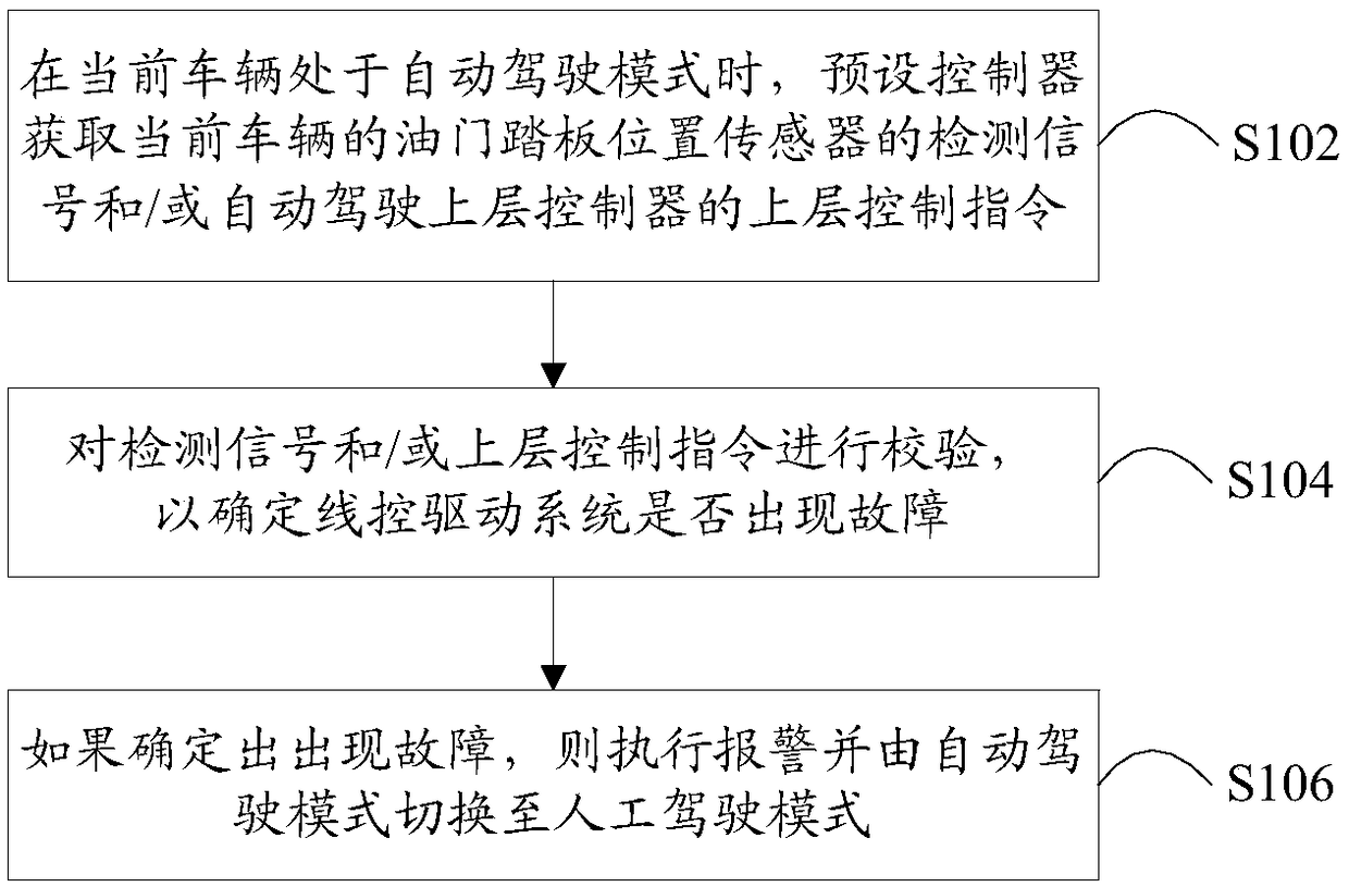
[0029] figure 1 It is a flow chart of a drive method for a drive-by-wire drive system provided according to an embodiment of the present invention, such as figure 1 As shown, the method includes the following steps:

[0030] Step S102, when the current vehicle is in the automatic driving mode, the preset controller acquires the detection signal of the accelerator pedal position sensor of the current vehicle and / or the upper-level control instruction of the automatic driving upper-level controller;

[0031] Step S104, verifying the detection signal and / or the upper-layer control c...

Embodiment 2

[0113] The embodiment of the present invention also provides a drive-by-wire system. The following describes the drive-by-wire system provided by the embodiment of the present invention in detail.

[0114] Figure 6 It is a schematic structural diagram of a drive-by-wire system provided according to an embodiment of the present invention.

[0115] Such as Figure 6 As shown, the drive-by-wire system mainly includes: an accelerator pedal position sensor 10, a preset controller 20 and an automatic driving upper layer controller 30, wherein the preset controller 20 is arranged on the accelerator pedal position sensor 10 and the engine management system 50 ( Engine Management System, referred to as EMS), the preset controller includes an automatic driving underlying drive controller 201 and / or a check controller 202;

[0116] The preset controller 20 is used to obtain the detection signal of the accelerator pedal position sensor 10 of the current vehicle and / or the upper layer c...


PUM


Abstract

Te invention provides a driving method of a drive-by-wire driving system and the drive-by-wire driving system, and relates to the technical field of automatic driving. A corresponding controller is arranged between an accelerator pedal position sensor and an engine management system in advance, and the controller can be used for checking the accelerator pedal position sensor and / or an upper-layercontrol instruction of an automatic driving upper-layer controller, so that when the accelerator pedal position sensor and / or the upper-layer control instruction are / is abnormal, an automatic drivingmode is switched to an artificial driving mode in time, the safety of automatic driving is guaranteed, and further the technical problem that in the prior art, safety of automatic driving is low due to the fact that fault detection cannot be carried out on the upper-layer control instruction of the automatic driving upper-layer controller and / or the accelerator pedal position sensor of a vehicle is solved.

Description

technical field [0001] The invention relates to the technical field of automatic driving, in particular to a driving method of a drive-by-wire drive system and a drive-by-wire system. Background technique [0002] During the development process of automatic driving, the requirements for the driving system include: the driving system can be developed and highly intervened; there is safety protection in case of unreasonable upper-level instructions or component failures; the ability to complete the mode switching between automatic driving and manual driving. [0003] The existing solutions mainly include: through the electronic throttle system adaptive cruise control (Adaptive Cruise Control referred to as ACC) interface or the traction control system (Acceleration Slip Regulation referred to as ASR) interface to indirectly control the throttle to realize the driving control in automatic driving; by adding The actuator (that is, the electric motor) controls the opening of the ...

Claims


Application Information

Patent Timeline
Patent Type & Authority Applications(China)
IPC IPC(8): B60W30/182B60W50/14
CPCB60W30/182B60W50/14B60W2050/143
Inventor 俞伟李亮康雅文张璞林甲胜
Owner TIANJIN TRINOVA AUTOMOTIVE TECH CO LTD
Why Eureka
Try Eureka