Glass sucking device

A suction device, glass technology, applied in transportation and packaging, conveyor objects, furnaces, etc., can solve the problems of glass damage placement, inconvenient detection process, affecting detection efficiency, etc., to achieve accurate dripping operation and dripping action. And the effect of placing the action is coherent and smooth, and the operation is simple and efficient.

Pending Publication Date: 2018-10-12
东莞市臻精智能科技有限公司
View PDF20 Cites 2 Cited by
  • Summary
  • Abstract
  • Description
  • Claims
  • Application Information

AI Technical Summary

Problems solved by technology

The process of its use requires the staff to place the glass to be tested in the detection area where the detection liquid has been dripped, and the manual placement operation may cause damage to the glass or the placement position is not stable enough to affect the detection effect
Manual placement of glass takes a long time, is low in efficiency, and has a low degree of automation. It requires frequent removal and placement of glass. The detection process is not convenient enough and it is easy to cause damage.
The glass to be tested is easy to stick to the detection platform due to the detection liquid, which is not convenient for manual handling, which will also affect the detection efficiency

Method used


Image

  • Glass sucking device
  • Glass sucking device
  • Glass sucking device

Examples


Embodiment Construction

[0030] In order to further illustrate the above-mentioned purpose, technical scheme and effect of the present invention, the present invention will be described below in conjunction with the accompanying drawings and relevant known technical knowledge through the embodiments:

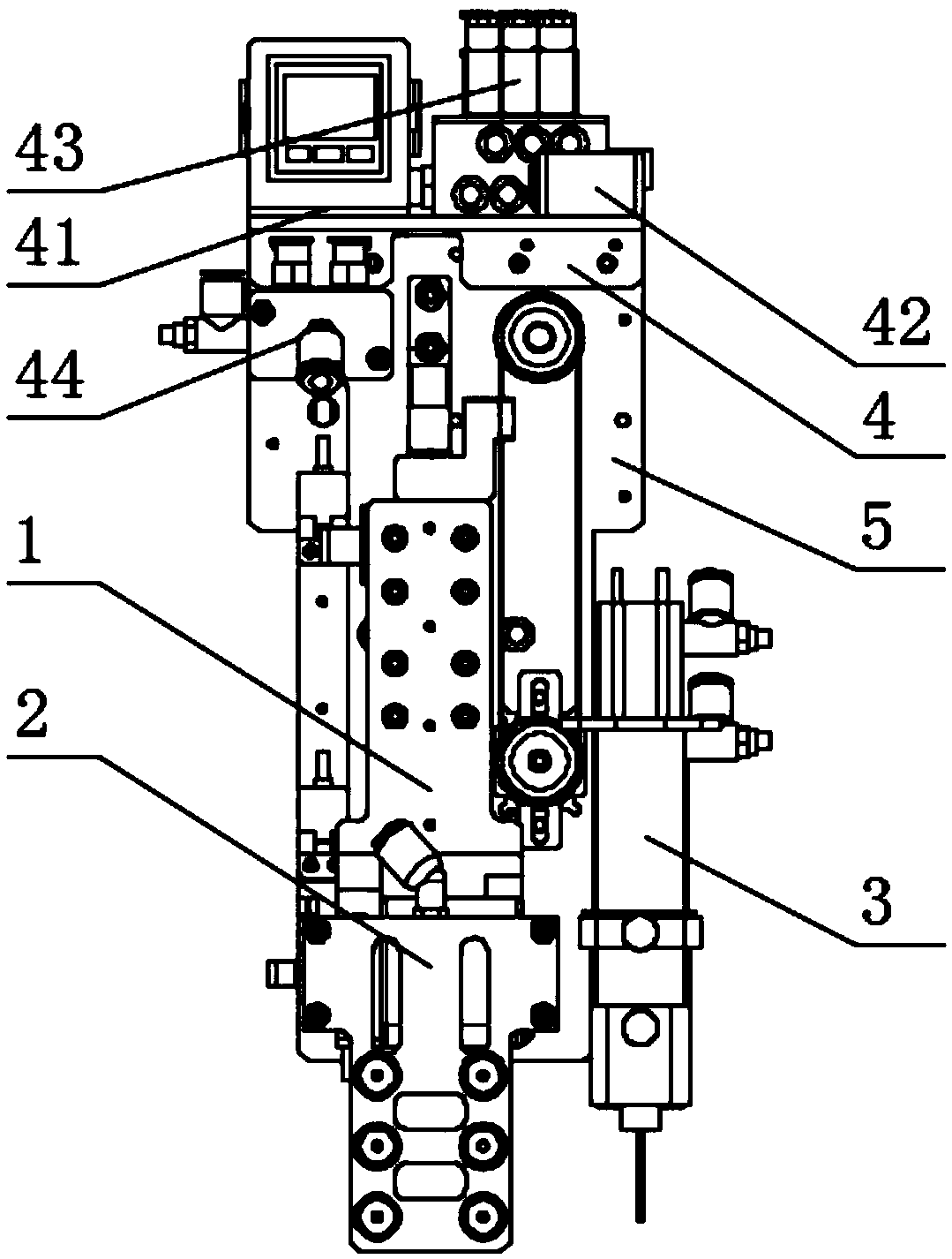
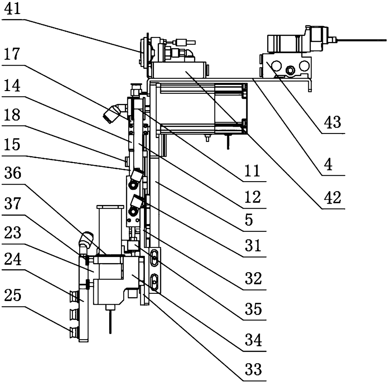
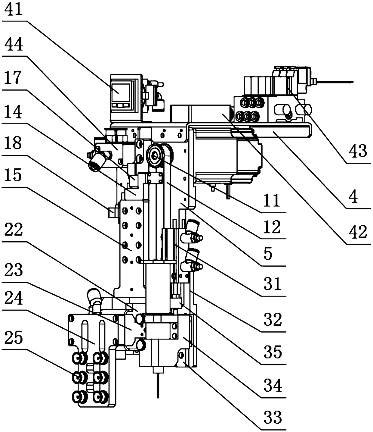
[0031] like figure 1 As shown, a glass suction device in this embodiment includes a fixed base plate 5, a transmission assembly 1, a rotating assembly 2 and a dispensing assembly 3; the transmission assembly 1 is arranged on the fixed base plate 5, and the fixed base plate 5 is fixed to an X-axis moving assembly , can be driven by the X-axis moving assembly to move horizontally; the rotating assembly 2 is fixedly connected to the transmission assembly 1, and the transmission assembly 1 moves the rotating assembly 2 up and down; the rotating assembly 2 is provided with a suction cup 25 to absorb glass, and the rotating assembly 2 can drive The sucked glass is rotated at a certain angle to complete the po...


PUM


Abstract

The invention discloses a glass sucking device and belongs to the field of automatic detection equipment. The glass sucking device comprises a fixing base plate, a transmission component, a rotating component and a glue dispensing component; the transmission component is arranged on the fixing base plate; the fixing base plate can be driven to move horizontally by an X-axis moving component; the rotating component is fixedly connected with the transmission component; the transmission component is used for driving the rotating component to move up and down; the rotating component is provided with a sucking disc for sucking glass; the rotating component can be used for driving the sucked glass to rotate at a certain angle to implement posture regulation so that the glass can be convenientlyplaced; and the glue dispensing component is fixedly connected with the fixing base plate and is arranged adjacent to the transmission component so that the glass sucked by the sucking disc can be placed after detecting liquid is dripped. According to the glass sucking device disclosed by the invention, the sucking disc and the rotating component are arranged for sucking the glass rotationally; adisplacing component is used for driving the glass to move; the glue dispensing component and the transmission component are arranged integrally to simplify the operation process; and thus various inconveniences caused by an existing method of picking the glass with hands are prevented.

Description

【Technical field】 [0001] The invention relates to the field of automatic detection equipment, in particular to a glass suction device for transporting and flipping materials to be detected. 【Background technique】 [0002] In the inspection process of tempered glass, a surface stress meter is usually used to measure the surface stress of chemically strengthened and physically strengthened glass. The process of its use requires the staff to place the glass to be tested in the detection area where the detection liquid has been dripped, and the manual placement operation may cause damage to the glass or the placement position is not stable enough to affect the detection effect. Manually placing glass takes a long time, is inefficient, and has a low degree of automation. It requires frequent picking and placing of glass. The inspection process is not convenient enough and it is easy to cause damage. The glass to be tested is easy to stick to the detection platform due to the det...

Claims


Application Information

Patent Timeline
Patent Type & Authority Applications(China)
IPC IPC(8): B65G49/06
CPCB65G49/061
Inventor 徐林蒋韶华陈萍吴良辉
Owner 东莞市臻精智能科技有限公司
Why Eureka
Try Eureka