Exhaust gas purifying device

a technology of exhaust gas and purifying device, which is applied in the direction of mechanical equipment, machines/engines, transportation and packaging, etc., can solve the problems of reducing the design manpower of assembling the dpf to the engine, the inability to improve the purification performance of the exhaust gas, and the inability to reduce the design manpower of the dpf, so as to improve the maintenance workability of the gas purifying body, the inside case and the outside case can be easily attached

Active Publication Date: 2014-12-23
YANMAR POWER TECHNOLOGY CO LTD
View PDF11 Cites 5 Cited by
  • Summary
  • Abstract
  • Description
  • Claims
  • Application Information

AI Technical Summary

Benefits of technology

[0032]According to the sixth aspect of the present invention, the space is formed between the outer peripheral side of the other of the inside case in which the other end side of the heat shield case is extended, and the inner peripheral side of the heat shield case. Accordingly, it is possible to easily make the other of the inside case come in and out with respect to the heat shield case, and it is possible to easily bond or separate the inside cases and the outside cases. It is possible to improve a maintenance workability of the gas purifying bodies or the exhaust gas sensor.
[0033]According to the seventh aspect of the present invention, the other end side of the heat shield case which is extended to the outside surface of the other of the inside case is coupled to the flange body for connecting the outside case. Accordingly, it is possible to easily prevent the exhaust gas from leaking from the gas purifying body toward the outside case. On the basis of the heat insulating action of the outside case and the heat shield case, it is possible to reduce the lowering of the exhaust gas temperature of the gas purifying body and the rise of the surface temperature of the outside case.
[0034]According to the eighth aspect of the present invention, the inside case, the heat shield case and the outside case are provided as the three-layer structure, the side end of the heat shield case is formed shorter than the side end of the outside case, and the side end of the inside case is formed shorter than the side end of the heat shield case. Accordingly, it is possible to reduce the temperature lowering of the exhaust gas, and it is possible to improve a treating efficiency of the particulate matter in the exhaust gas. It is possible to reduce the rise of the surface temperature of the outside case, and it is possible to improve a workability of a maintenance of a diesel engine which is necessary during an operation.
[0035]According to the ninth aspect of the present invention, the exhaust gas pressure sensor is arranged in the outside surface of the outside case, the pipe joint for connecting the sensor piping is fastened to the sensor boss body via the pipe joint bolt, and the exhaust gas pressure sensor is connected to the sensor boss body via the sensor piping. Accordingly, it is not necessary to evaluate an initial setting (adjusting) condition of the exhaust gas pressure sensor per the plural specifications of engines or ma...

Problems solved by technology

In other words, since the exhaust gas temperature in the inner portion of the case is lowered, the particulate matter in the exhaust gas tends to clog the soot filter, and it is necessary to regenerate the soot filter at a high frequency, so that there is such a problem that it is impossible to improve a purifying performance of the exhaust gas.
On the other hand, since the outer surface of the case comes to a high temperature, it is necessary to carry out a maintenance of the diesel engine after the case is cooled down, so that there is such a problem that it is impossible to improve a handling workability.
Further, in the prior art, since it is necessary to evaluate an initial setting (adjusting) condition of the exhaust gas pressure sensor per plural specifications of engines or machine bodies, in the case that the exhaust gas pressure sensor for detecting the pressure of the exhaust gas is provided in the engine or the machine body side, there is such a problem that it is impossible to reduce an evaluating man power ...

Method used


Image

  • Exhaust gas purifying device
  • Exhaust gas purifying device
  • Exhaust gas purifying device

Examples


Embodiment Construction

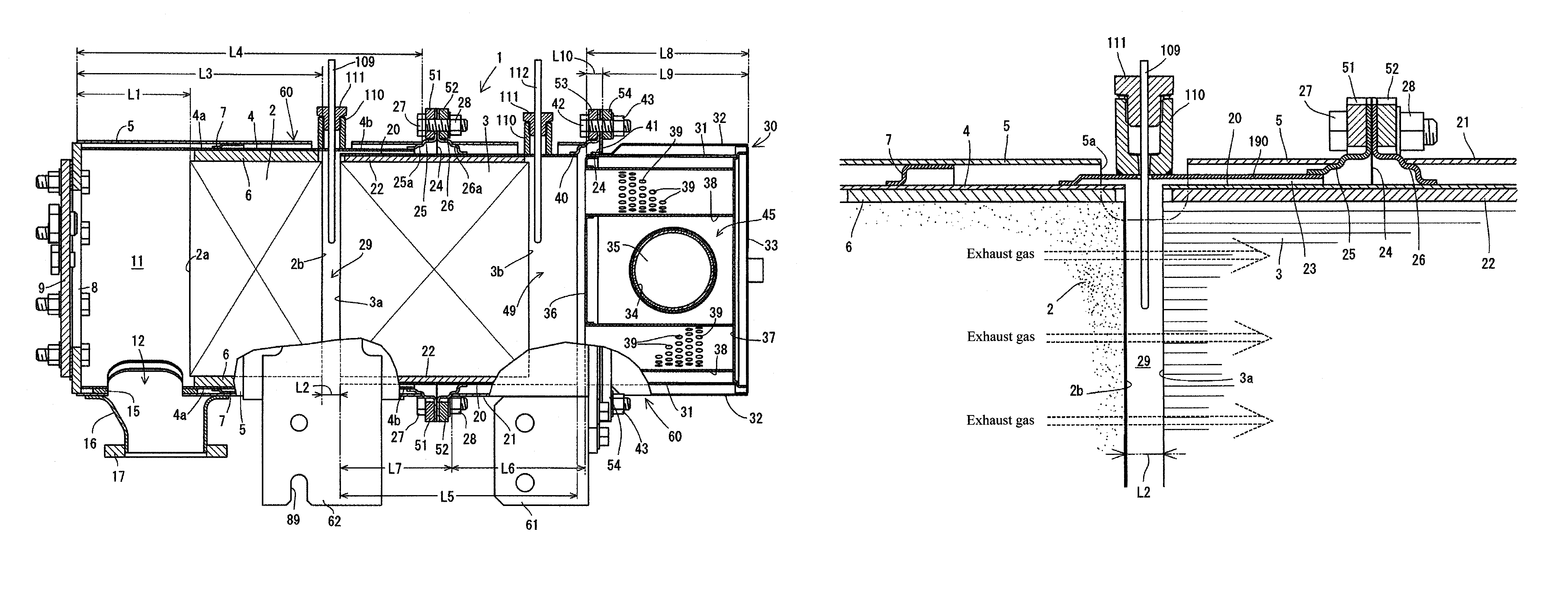
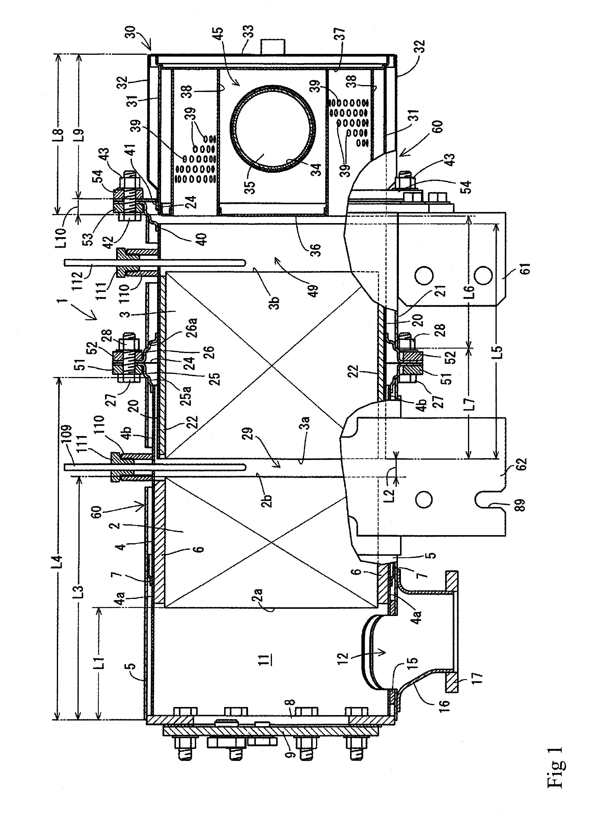
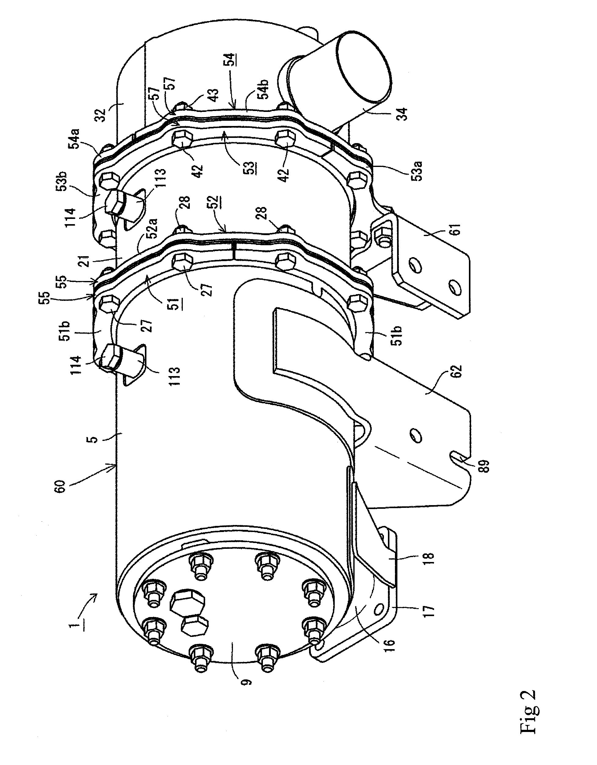
[0063]A description will be given below of a first embodiment of an exhaust gas purifying device obtained by embodying the present invention on the basis of the accompanying drawings with reference to FIG. 1 to FIG. 20. It is provided with a continuous regeneration type diesel particulate filter 1 (hereinafter, refer to as DPF 1) as an exhaust gas purifying device. It is structured such that the DPF 1 reduces a carbon monoxide (CO) and a hydro carbon (HC) in an exhaust gas of a diesel engine 70, in addition to a removal of a particulate matter (PM) in the exhaust gas of the diesel engine 70.

[0064]As shown in FIG. 1, FIG. 6 and FIG. 13, the DPF 1 serving as the exhaust gas purifying device is provided for collecting the particulate matter (PM) in the exhaust gas. The DPF 1 is structured as an approximately cylindrical shape which extends long in a lateral direction which intersects an output shaft (a crank shaft) of the diesel engine 70 in a plan view. The DPF 1 is arranged on a flyw...


PUM


Abstract

Provided is an exhaust gas purifying device which can improve handling work ability such as maintenance of an engine while it can improve a purifying performance of an exhaust gas of the engine. The exhaust gas purifying device is provided with a plurality of gas purifying bodies which purifies the exhaust gas discharged by the engine, a plurality of inside cases which are inward provided with the gas purifying bodies, and outside which are inward provided with the inside cases. An outlet end portion of an inside case in an exhaust gas upstream side and an inlet end portion of an in an exhaust gas downstream side are superposed as a double structure. Sensor boss bodies for supporting exhaust gas sensors are arranged in an outside surface of the outlet end portion or the inlet end portion of the double structure. The sensor boss bodies are extended to an outside direction of the outside case.

Description

BACKGROUND OF THE INVENTION[0001]The present invention relates to an exhaust gas purifying device which is mounted to a diesel engine or the like, and more particularly to an exhaust gas purifying device which removes a particulate matter (a soot and a particulate) and the like which are included in an exhaust gas.[0002]Conventionally, there has been known a technique which is provided in an exhaust route of a diesel engine with a diesel particulate filter (hereinafter, refer to as DPF) as an exhaust gas purifying device (an after treatment device), for purifying an exhaust gas which is discharged form the diesel engine by the DPF (refer, for example, to patent document 1).[0003]Further, in the DPF, there has been also known a technique which is provided with a temperature sensor which detects a temperature of an exhaust gas discharged from a diesel engine, and a pressure sensor which detects a pressure of the exhaust gas discharged from the diesel engine (refer, for example, to pat...

Claims


Application Information

Patent Timeline
IPC IPC(8): F01N13/00F01N3/00F01N13/02
CPCF01N2260/20F01N13/00F01N13/0097F01N13/02F01N13/008F01N13/1805F01N2470/18F01N13/1855Y10T137/8376F01N13/143F01N3/00F01N3/02F01N3/021F01N3/20F01N3/28F01N13/08
Inventor MITSUDA, MASATAKA
Owner YANMAR POWER TECHNOLOGY CO LTD
Why Eureka
Try Eureka