
Inspection device and inspection method for truss bridges

An inspection device and truss technology, applied in bridges, bridge parts, bridge construction, etc., can solve the problems of low inspection and maintenance efficiency, cumbersome walking procedures, poor safety performance, etc., and achieve high inspection efficiency, cost reduction, and fast running speed. Effect

Active Publication Date: 2020-12-29
ZHUZHOU TIMES NEW MATERIALS TECH
View PDF6 Cites 0 Cited by
  • Summary
  • Abstract
  • Description
  • Claims
  • Application Information

AI Technical Summary

Problems solved by technology

[0003] However, there are still some problems with the above way of setting the track for steel truss bridges
For example, tracks, pedestals and their fixings need to be laid on top of the full bridge, which leads to long construction period and high cost
In addition, although the method of only welding the connectors does not require the laying of tracks for the whole bridge, the walking process is cumbersome and the speed is slow. Because of its few fixed points, as long as there is a problem with one fulcrum during the movement, it may lead to catastrophic consequences. Its stability is poor , poor safety performance, and low inspection and maintenance efficiency

Method used


Image

  • Inspection device and inspection method for truss bridges
  • Inspection device and inspection method for truss bridges
  • Inspection device and inspection method for truss bridges

Examples


Embodiment Construction

[0027]The present invention will be described in more detail below through the drawings. It should be noted that the azimuth term “lateral” in the following refers to the horizontal direction of the cross section of the truss bridge, and “longitudinal” refers to the extension direction of the truss bridge.

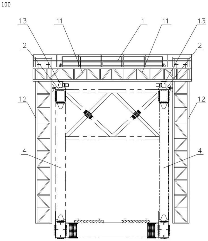
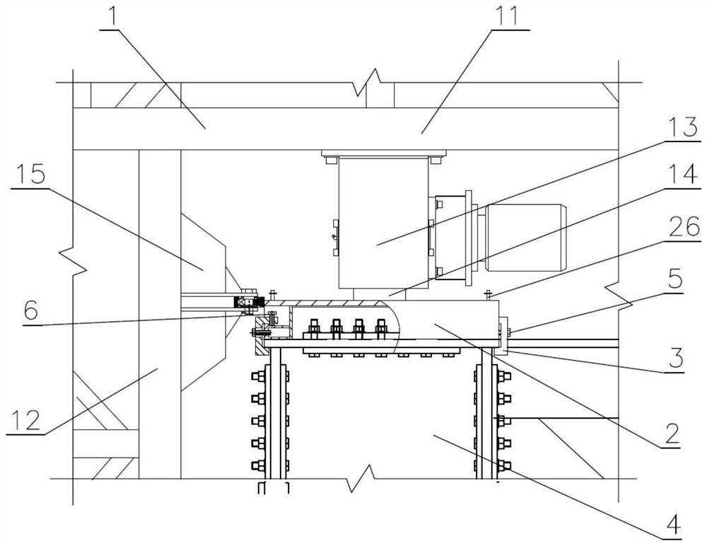
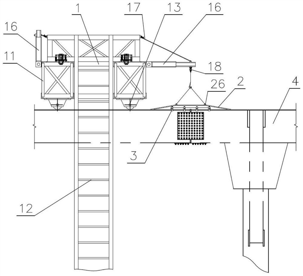
[0028]figure 1 A front view of the inspection device 100 for a truss bridge according to the present invention is shown. Such asfigure 1 As shown, the inspection device 100 includes an inspection vehicle 1. The inspection vehicle 1 includes a traveling mechanism 13. In one embodiment, the inspection vehicle 1 is provided with four traveling mechanisms 13. Such asfigure 2 As shown, a traveling wheel 14 is provided below the traveling mechanism 13. The inspection vehicle 1 drives the traveling wheels 14 through the traveling mechanism 13 to move longitudinally on the top of the upper chord of the steel truss beam 4 of the truss bridge. Horizontal trusses 11 are fixedly placed on the ...


PUM


Abstract

The invention provides an inspecting apparatus for a truss bridge. The inspecting apparatus for the truss bridge comprises an inspecting vehicle, a running mechanism, a rotating suspension arm and a node-crossing piece, wherein the inspecting vehicle comprises a horizontal truss and a vertical truss which is used for an inspecting personnel to inspect a passage in the side surface of the bridge; the running mechanism is used for driving the inspecting vehicle to move in a longitudinal direction; the horizontal truss is fixedly placed on the running mechanism; the rotating suspension arm is arranged on the side surface of the horizontal truss; the rotating suspension arm is in the vertical direction when being in a non-working state; the rotating suspension arm is in the horizontal direction when being in a working state; and the node-crossing piece is arranged at a node of the truss bridge and used for the inspecting vehicle to pass through the node, wherein the node-crossing piece canbe taken off or placed when the rotating suspension arm is in the working state. The invention further provides an inspecting method for the truss bridge; and by using the inspecting device, the truss bridge is inspected.

Description

Technical field[0001]The invention relates to a bridge inspection device, in particular to an inspection device for a truss bridge. The invention also relates to an inspection method for truss bridges.Background technique[0002]At present, steel truss bridges are widely used in bridge construction. During the application of steel truss bridges, regular inspections and maintenance are required. Because the steel truss beam is mainly composed of rods, the connections between the rods are mostly connected by gusset plates and bolts. In the process of inspection and maintenance, in order to cross the gusset plate, the prior art adopts a method in which a pedestal is used to raise the track foundation at intervals on the top of the upper chord of the steel truss beam and then the track is placed on the pedestal. Or use the longitudinal bridge direction to weld the connecting parts on the top chord of the steel truss beam at intervals, and then set a shorter walking beam under the inspecti...

Claims


Application Information

Patent Timeline
Patent Type & Authority Patents(China)
IPC IPC(8): E01D19/10
CPCE01D19/106
Inventor 李文斌刘军梅仕伟宁响亮李典计
Owner ZHUZHOU TIMES NEW MATERIALS TECH
Learn More