Sealing structure for compressor plunger

A sealing structure and compressor technology, applied in the field of compressors, can solve the problems of low compensation performance, poor sealing effect, and large contact area of ​​sealing rings, and achieve the effects of improving sealing performance, reducing contact area, and reducing frictional heat generation Effect

Pending Publication Date: 2018-10-12
杭州新亚低温科技有限公司
View PDF7 Cites 4 Cited by
  • Summary
  • Abstract
  • Description
  • Claims
  • Application Information

AI Technical Summary

Problems solved by technology

[0003] The existing sealing packing is mainly a V-shaped or O-shaped sealing ring. The sealing ring has a large contact area with the side wall of the plunger. When the plunger and the sealing ring slide relative to each other, it is easy to generate heat, and it can only be sealed on one side. The sealing effect is poor, and the compensation performance of the V-shaped or O-shaped structure of the sealing ring is low

Method used


Image

  • Sealing structure for compressor plunger
  • Sealing structure for compressor plunger

Examples


Embodiment Construction

[0026] The present invention will be described in detail below in conjunction with the accompanying drawings and embodiments.

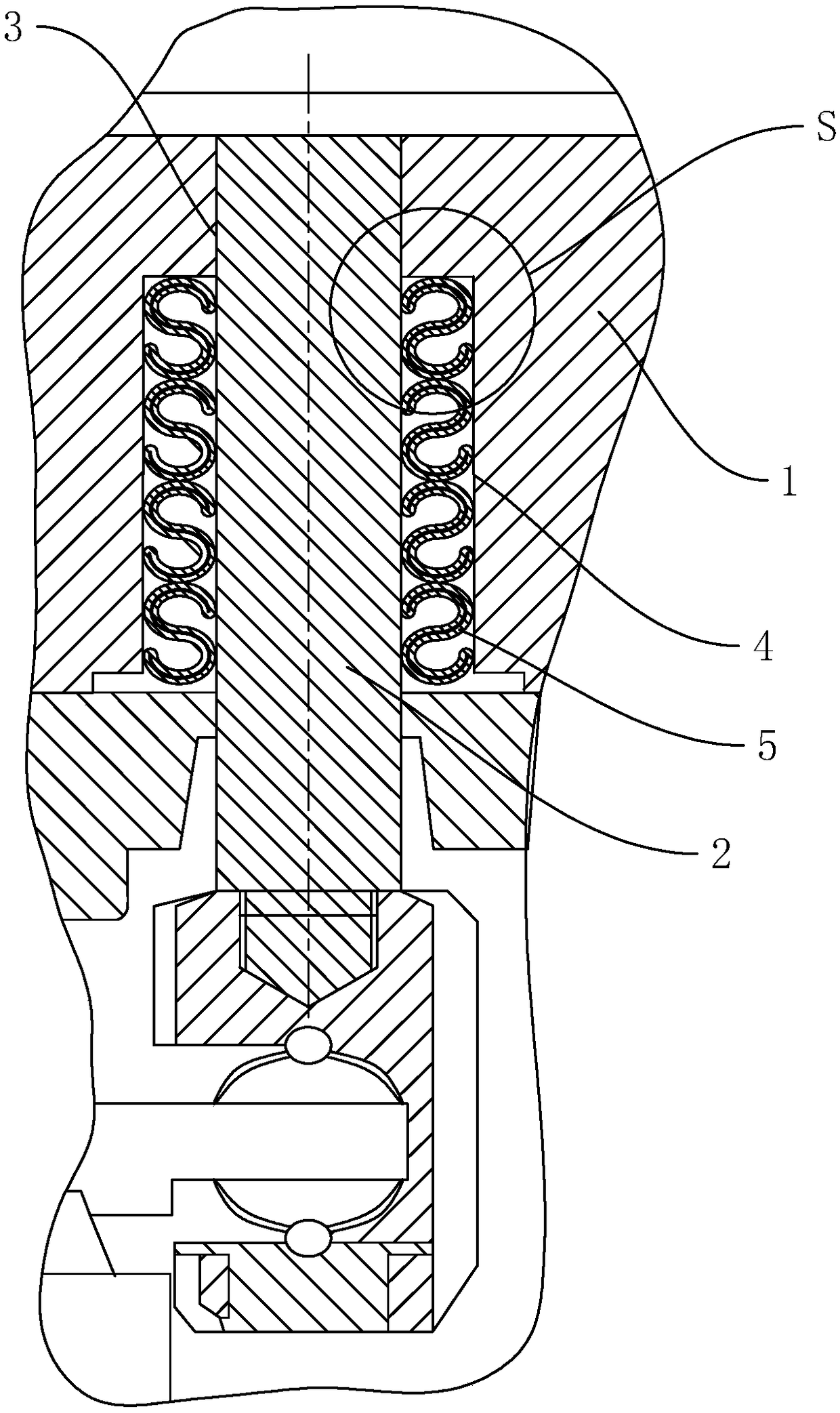
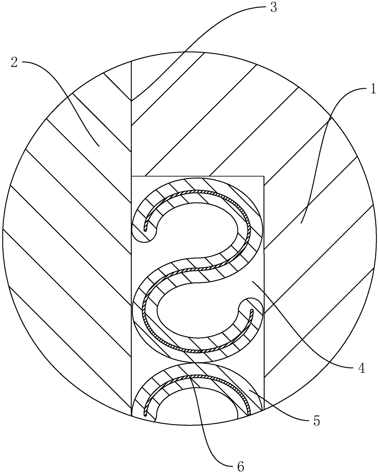
[0027] A sealing structure for a compressor plunger, such as figure 1 As shown, it includes a cylinder block 1 and a plunger 2. The cylinder block 1 is provided with a plunger hole 3 for the plunger 2 to pass through, and the side wall of the plunger hole 3 is provided with a sealing groove 4 for the installation of the sealing packing. A sealing ring 5 is installed in the groove 4, and the section of the sealing ring 5 is arranged in an S shape. The inner wall of the sealing ring 5 is attached to the side wall of the plunger 2 , the outer wall of the sealing ring 5 is attached to the side wall of the sealing groove 4 , and the end surface of the sealing ring 5 abuts against the bottom surface of the sealing groove 4 . In this way, the S-shaped sealing ring 5 can ensure that the gap between the plunger 2 and the plunger hole 3 is sealed to achieve th...


PUM


Abstract

The invention discloses a sealing structure for a compressor plunger, and aims at improving the sealing performance, and reducing the contact area of a sealing ring and the plunger. The essential of the technical scheme is as follows: the sealing structure for the compressor plunger comprises a cylinder body and a plunger, wherein the cylinder body is provided with a plunger hole allowing the plunger to penetrate; a sealing groove is formed in the sidewall of the plunger hole; the sealing ring is arranged in the sealing groove; the section of the sealing ring is configured to be S-shaped; theinner wall of the sealing ring is bonded onto the sidewall of the plunger; and the outer sidewall of the sealing ring is bonded onto the sidewall of the sealing groove. The sealing structure for the compressor plunger is capable of improving the sealing performance, and reducing the contact area of the sealing ring and the plunger.

Description

technical field [0001] The present invention relates to a compressor, more specifically, it relates to a sealing structure of a compressor plunger. Background technique [0002] In order to prevent the gas from escaping from the gap between the plunger and the cylinder block, a sealing packing is often arranged between the plunger and the cylinder block. [0003] The existing sealing packing is mainly a V-shaped or O-shaped sealing ring. The sealing ring has a large contact area with the side wall of the plunger. When the plunger and the sealing ring slide relative to each other, it is easy to generate heat, and it can only be sealed on one side. The sealing effect is poor, and the compensation performance of the V-shaped or O-shaped structure of the sealing ring is low. [0004] Therefore, a new solution needs to be proposed to solve this problem. Contents of the invention [0005] In view of the deficiencies in the prior art, the purpose of the present invention is to ...

Claims


Application Information

Patent Timeline
Patent Type & Authority Applications(China)
IPC IPC(8): F16J15/3284F16J15/3268F16J15/3252F04B39/00F04B39/12
CPCF04B39/00F04B39/122F16J15/3252F16J15/3268F16J15/3284
Inventor 安丽丽章轶明刘易孙立东马晓燕张笑波
Owner 杭州新亚低温科技有限公司
Why Eureka
Try Eureka