
Cantilever beam for working of equipment inside pipeline or tank body

A technology of internal equipment and cantilever beams, applied in the direction of mechanical equipment, supporting machines, machine tables/supports, etc., can solve the problems of large space occupation, increase of total investment cost, lengthening of flaw detection room length, etc., to improve efficiency and prolong use Effect of life and weight reduction

Pending Publication Date: 2018-10-12
SHANGHAI KINGS AUTOTECH
View PDF8 Cites 0 Cited by
  • Summary
  • Abstract
  • Description
  • Claims
  • Application Information

AI Technical Summary

Problems solved by technology

[0002] For equipment that is similar to long workpieces such as pipes or tanks, it is necessary to install the equipment on the cantilever when inspecting its interior, and then place the detection equipment in the pipe or tank for inspection by telescopic; because some pipes or tanks are longer , so the length of the cantilever is required to be consistent with the length of the detected workpiece; since the cantilever needs to be equipped with testing equipment and walking equipment, the weight of the cantilever will increase, which will reduce the detection accuracy of the equipment on the one hand, and on the other hand, due to the lengthening of the flaw detection The length of the room increases the total investment cost, resulting in a large space occupation, which brings inconvenience to the workpiece detection work

Method used


Image

  • Cantilever beam for working of equipment inside pipeline or tank body
  • Cantilever beam for working of equipment inside pipeline or tank body
  • Cantilever beam for working of equipment inside pipeline or tank body

Examples


Embodiment Construction

[0021] In order to make the technical means, technical features, invention objectives and technical effects realized by the present invention easy to understand, the present invention will be further described below in conjunction with specific illustrations.

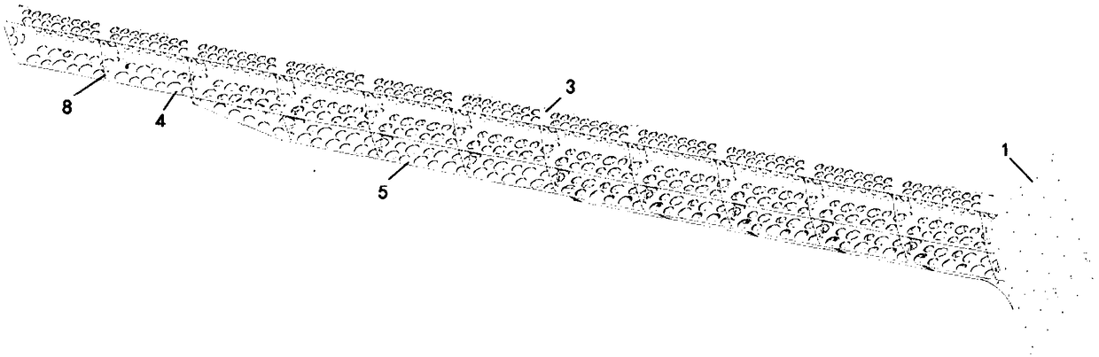
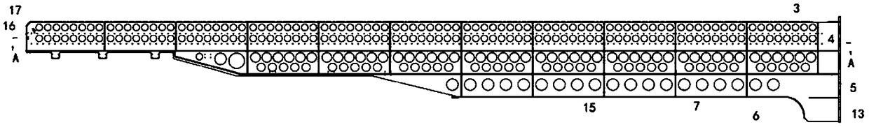
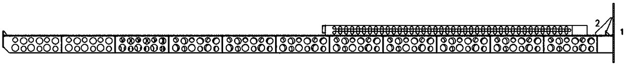
[0022] Such as Figure 1 to Figure 6 As shown, it is a cantilever beam used for pipeline or tank internal equipment work of the present invention, including a connecting plate 1, a main beam plate 2, an upper flat beam 3, a middle flat beam 4, a lower flat beam 5 and a short support flat Beam 6.

[0023] The right end surface of the main beam plate 2 in the present invention is vertically connected with the inner end surface of the connecting plate 1 . The sides of the upper flat beam 3 , the middle flat beam 4 , the lower flat beam 5 and the short support flat beam 6 are vertically arranged on the inner side of the main beam plate 2 .

[0024] The main beam plate 2 in the present embodiment is equal to the length of ...


PUM


Abstract

The invention discloses a cantilever beam for working of equipment inside a pipeline or a tank body. The cantilever beam comprises a connecting plate and is characterized by further comprising a mainbeam plate, an upper flat beam, a middle flat beam, a lower flat beam and a short supporting flat beam; one end of the main beam plate is connected with the inner end face of the connecting plate; side surfaces of the upper flat beam, the middle flat beam, the lower flat beam and the short supporting flat beam are vertically arranged on the inner side surface of the main beam plate, and are vertically connected with the inner side surface of the main beam plate; and a plurality of weight reducing holes are formed in the main beam plate, the upper flat beam, the middle flat beam, the lower flatbeam and the short supporting flat beam in the length direction. According to the cantilever beam, the plurality of rows of weight reducing holes are formed in the main beam plate, the upper flat beam, the middle flat beam, the lower flat beam in the length direction, so that the self weight is greatly reduced, the internal detection efficiency of workpieces is improved, and the service life of the whole device is prolonged.

Description

technical field [0001] The invention relates to a cantilever beam, in particular to a cantilever beam used for working equipment inside a pipeline or a tank. Background technique [0002] For equipment that is similar to long workpieces such as pipes or tanks, it is necessary to install the equipment on the cantilever when inspecting its interior, and then place the detection equipment in the pipe or tank for inspection by telescopic; because some pipes or tanks are longer , so the length of the cantilever is required to be consistent with the length of the detected workpiece; since the cantilever needs to be equipped with testing equipment and walking equipment, the weight of the cantilever will increase, which will reduce the detection accuracy of the equipment on the one hand, and on the other hand, due to the lengthening of the flaw detection The length of the room increases the total investment cost, resulting in a large space occupation, which brings inconvenience to t...

Claims


Application Information

Patent Timeline
IPC IPC(8): F16M13/02F16M11/42
CPCF16M11/425F16M13/02
Inventor 付智森唐昭华
Owner SHANGHAI KINGS AUTOTECH
Features
  • Generate Ideas
  • Intellectual Property
  • Life Sciences
  • Materials
  • Tech Scout
  • Unparalleled Data Quality
  • Higher Quality Content
  • 60% Fewer Hallucinations
Learn More