
Battery cooling device for new energy vehicle

A new energy vehicle and cooling device technology, applied in the direction of secondary batteries, battery pack components, circuits, etc., can solve the problems of increased battery heat generation, reduced battery life, and increased battery, achieving simple structure, extended life, The effect of easy assembly

Active Publication Date: 2018-10-12
安徽上造智能设备科技有限公司
View PDF5 Cites 2 Cited by
  • Summary
  • Abstract
  • Description
  • Claims
  • Application Information

AI Technical Summary

Problems solved by technology

The battery used in electric vehicles will generate heat during charging and discharging. In order to increase the storage capacity of the battery, the simplest and direct way for electric vehicles is to increase the capacity of the battery and increase the volume of the battery to obtain a high storage capacity of the battery. Or increase the number of batteries and increase the power, so the heat generated by the battery will increase, and the heat will not flow out in time, which will greatly affect the performance of the battery and reduce the service life of the battery

Method used

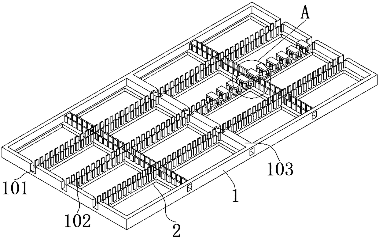
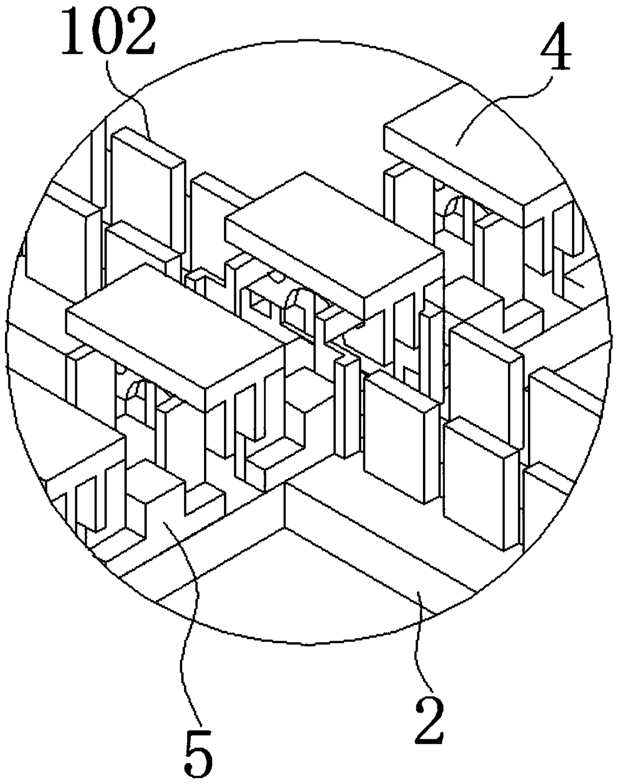
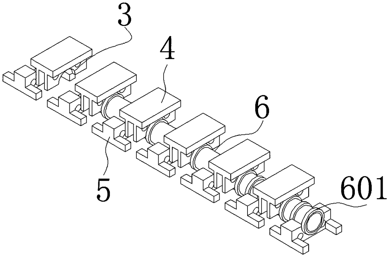

Image

  • Battery cooling device for new energy vehicle
  • Battery cooling device for new energy vehicle
  • Battery cooling device for new energy vehicle

Examples


Embodiment Construction

[0021] The following will clearly and completely describe the technical solutions in the embodiments of the present invention with reference to the accompanying drawings in the embodiments of the present invention. Obviously, the described embodiments are only some, not all, embodiments of the present invention. Based on the embodiments of the present invention, all other embodiments obtained by persons of ordinary skill in the art without creative efforts fall within the protection scope of the present invention.

[0022] In describing the present invention, it is to be understood that the terms "opening", "upper", "lower", "thickness", "top", "middle", "length", "inner", "surrounding" etc. Indicating orientation or positional relationship is only for the convenience of describing the present invention and simplifying the description, and does not indicate or imply that the components or elements referred to must have a specific orientation, be constructed and operated in a sp...


PUM


Abstract

The invention discloses a battery cooling device for a new energy vehicle and belongs to the technical field of power supply cooling. The battery cooling device comprises fastening blocks and bearingblocks for limiting a heat-conducting pipe, and a rectangular frame seat for fixing power supplies in groups, wherein each fastening block is an overall part formed by a pair of clamping plates and acover plate; each bearing block is an overall part formed by a rectangular block and two pairs of bearing feet; a C-shaped notch is formed in each rectangular block and each clamping plate separately;a plurality of fastening blocks and a plurality of bearing blocks are alternately matched in a gap between two rows of partition plates in sequence to form an open limiting channel; the heat-conducting pipe is arranged in the open limiting channel and provided with a row of positioning rings, wherein the heat-conducting pipe is matched into the C-shaped notches; one rectangular block or pair of clamping plates is matched between two adjacent positioning rings; criss-crossed bearing plates are arranged in the rectangular frame seat; and two rows of partition plates which are opposite two by two are arranged on the surface of each bearing plate. According to the battery cooling device, the power supplies of the vehicle are arranged in the rectangular frame seat in groups and a cooling pipeis arranged on the frame seat to cool the power supplies.

Description

technical field [0001] The invention belongs to the technical field of power supply cooling, in particular to a battery cooling device for new energy vehicles. Background technique [0002] With the development of science and technology, a large number of electric vehicles emerge on the market. The battery used in electric vehicles will generate heat during charging and discharging. In order to increase the storage capacity of the battery, the simplest and direct way for electric vehicles is to increase the capacity of the battery and increase the volume of the battery to obtain a high storage capacity of the battery. Or increase the number of batteries and increase the power, so that the heat generated by the battery increases, and the heat cannot be released in time, which will greatly affect the performance of the battery and reduce the service life of the battery. Contents of the invention [0003] The object of the present invention is to provide a battery cooling de...

Claims


Application Information

Patent Timeline
Patent Type & Authority Applications(China)
IPC IPC(8): H01M10/613H01M10/625H01M10/6557H01M10/653H01M2/10H01M50/20
CPCH01M10/613H01M10/625H01M10/653H01M10/6557H01M50/20Y02E60/10
Inventor 陈伟陈双龙
Owner 安徽上造智能设备科技有限公司
Learn More