
Method for repairing network hole of wireless sensor network based on direction of arrival

A wireless sensor and network hole technology, applied in wireless communication, network topology, network planning, etc., can solve problems such as difficulty in obtaining location information, difficult to achieve accuracy, and inability to solve uneven coverage of node density and holes

Active Publication Date: 2018-10-12
SOUTHEAST UNIV
View PDF4 Cites 0 Cited by
  • Summary
  • Abstract
  • Description
  • Claims
  • Application Information

AI Technical Summary

Problems solved by technology

[0003] Most of the existing WSNs hole repair methods require accurate node location information, which can be obtained by GPS or other methods, but in many cases it is difficult to obtain location information and the accuracy is difficult to meet the requirements of the method.
There are also some methods that require accurate relative distance information between nodes, and the accuracy of distance information in WSNs is also difficult to guarantee, and this type is also lacking in feasibility
There are also a small number of methods that only rely on whether the nodes can communicate, that is, only need the support of connectivity information between nodes to implement hole repair, but these methods usually cannot solve the problems caused by uneven node density in randomly arranged WSNs because they cannot mobilize mobile nodes. coverage hole problem
There are also some methods of this type that use a large number of repair nodes to win by quantity, and the efficiency and actual effect of implementation cannot be guaranteed.
Therefore, the hole repair strategy in the environment where the position information and relative distance information are unknown remains to be studied

Method used


Image

  • Method for repairing network hole of wireless sensor network based on direction of arrival
  • Method for repairing network hole of wireless sensor network based on direction of arrival
  • Method for repairing network hole of wireless sensor network based on direction of arrival

Examples


Embodiment Construction

[0045] The specific implementation manners of the present invention will be further described in detail below in conjunction with the accompanying drawings.

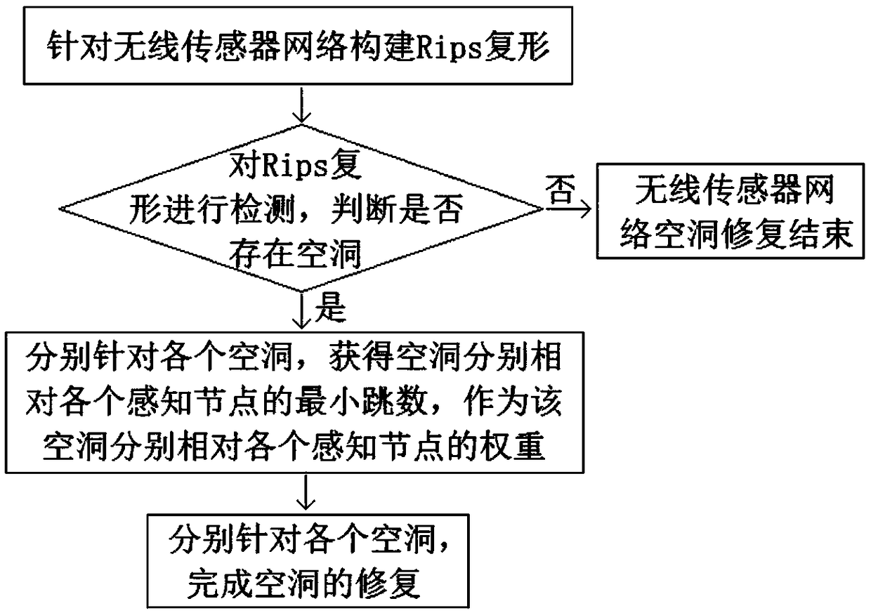
[0046] Such as figure 1 As shown, the present invention designs a method for repairing holes in a wireless sensor network based on the angle of arrival. The wireless sensor network includes each fixed sensing node and each mobile standby node with mobility, and the communication of each node Radius R C for its perceived radius R S 2 times of; described cavity repairing method comprises the steps:

[0047] Step A. Construct the Rips complex for the wireless sensor network, and use the hole boundary detection algorithm based on the coherence theory to detect the Rips complex to determine whether there is a hole, and if so, obtain the boundaries of each hole in the wireless sensor network, and then enter step B; Otherwise WSN hole repair is over.

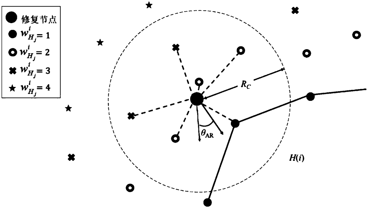
[0048] Step B. For each hole, obtain the minimum hop count of the hole r...


PUM


Abstract

The invention relates to a method for repairing a network hole of a wireless sensor network based on a direction of arrival. Firstly, based on a coverage hole boundary obtained by the existing method,a mobile standby node is selected according to the weight of a sensing node relative to the hole, the location of a repair node is judged by using the information of the direction of arrival of the adjacent sensing node, a heading direction is calculated, and the nodes are guided to enter the hole. In the hole, the repair node moves to an ideal location according to inter-node communication information and the information of the direction of arrival for repairing and updating the hole boundary, and iteration is performed continuously to execute the above process until the hole disappears. Themethod has the advantages that: on one hand, the method does not depend on the location information of the nodes or the distance information between the nodes, and can be applied to scenes with unknown information; and on the other hand, compared with the repair method of the same type, the computational complexity of the method is lower.

Description

technical field [0001] The invention relates to a method for repairing a hole in a wireless sensor network based on an angle of arrival, and belongs to the technical field of wireless communication. Background technique [0002] In the practical application of Wireless Sensor Networks (WSNs, Wireless Sensor Networks), due to various uncontrollable factors, coverage holes will inevitably appear in the target area. These factors may be due to the limited energy and unreliability of the wireless sensor nodes themselves. Sexuality may also come from external non-human or man-made damage. In order to maintain full coverage of the target area, a void repair method is essential. [0003] Most of the existing WSNs hole repair methods require accurate node location information, which can be obtained by GPS or other methods, but in many cases it is difficult to obtain location information and the accuracy is difficult to meet the requirements of the method. There are also some metho...

Claims


Application Information

Patent Timeline
Patent Type & Authority Applications(China)
IPC IPC(8): H04W16/18H04W24/04H04W64/00H04W84/18
CPCH04W16/18H04W24/04H04W64/006H04W84/18
Inventor 燕锋康泓董雨晴夏玮玮沈连丰胡静宋铁成
Owner SOUTHEAST UNIV
Learn More